
How to Compare Barrier Screws
When processors asked screw designer Robert Dray how to compare different types of barrier screws, he modeled melting capacity based on the biggest single factor, solids channel area. It gives a quick way to evaluate barrier-screw designs.


Computer simulations are based on the idea that the area of the primary melting channel is the key influence on a barrier screw's melting capacity, though depth of the channel also plays a role.
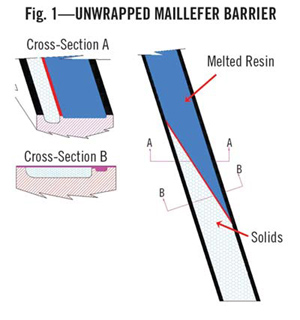
Screw Diam. = 4.492 in. Primary Lead = 4.500 in. Barrier Lead = 4.9038 in. Axial Barrier Length = 45 in. Helical Length = 148.75 in. Average Solids Channel Width = 1.9247 in. Melting Area = 1.9247 X 148.73 = 286.27 sq in. Melting Capacity (LDPE) = 539 lb/hr The Maillefer barrier, pateneted in 1967, was the first melt separation device. It retains solids in the primary channel, eliminating the break-up of the solids bed and improving melting capacity and melt quality.
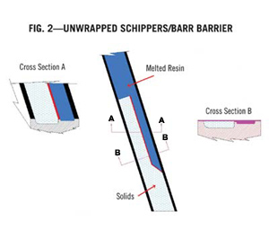
Screw Diam. = 4.492 in. Primary Lead = 4.500 in. Barrier Lead = 4.500 in. Axial Barrier Length = 45 in. Helical Length = 148.10 in. Primary Channel Width = 2.500 in. Melt Channel Width = 1.149 in. Melting Area = 2.500 X 148.10 = 370.25 sq in. Melting Capacity (LDPE) = 697 lb/hr The Schippers/Barr primary melting channel gets shallower as the auxiliary channel deepens. A straight primary flight increases melting area in contact with the barrel wall, relative to Maillefer's design.
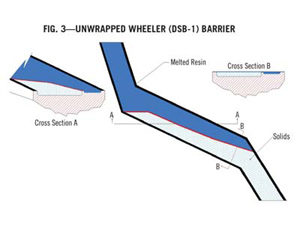
Screw Diam. = 4.492 in. Primary Lead = 6.30 in. Barrier Lead = Varies Axial Barrier Length = 45 in. Helical Length = 107.42 in. Average Channel Width = 3.053 in. Melting Area = 3.053 X 107.42 = 328 sq in. Melting Capacity (LDPE) = 617 lb/hr Wheeler's DSB-1 barrier for Davis-Standard borrows from Maillefer, Schippers/Barr, and Dray. It uses three different lead widths, which reduces the melting area.
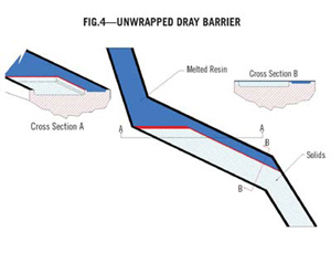
Screw Diam. = 4.492 in. Primary Lead = 6.75 in. Barrier Lead = 6.75 in. Axial Barrier Length = 45 in. Helical Length = 104.29 in. Primary Channel Width = 4.0883 in. Melting Area = 4.0883 X 104.29 = 426.37 sq in. Melting Capacity (LDPE) = 798 lb/hr The width of Dray's primary channel carrying the solids stays the same even after it joins the auxiliary channel, allowing a larger melting area than other barrier designs.
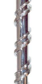
Extruder feed-screw design, more than any other part of an extrusion system, determines the productivity and quality of the extruded product. Screw designers are constantly asked to improve output quantity without sacrificing quality—or to improve both at the same time. Barrier-type feed screws are the most widely used designs in high-output, high-quality extrusion. In applications that also require low melt temperature, such as blown film, they are the standard.
Over the years, basic barrier-screw designs have remained fairly constant. For decades there were three basic patents and a half dozen major improvement patents, all of which have long been in the public domain. A couple of them evolved into mixing sections, but most of these designs are available in more or less their original form from a variety of manufacturers today. Processors, however, have little ability to evaluate and compare their performance, short of trial and error.


Modeling melting capacity
A computer simulation was developed to provide such a vehicle for comparison. It's a straightforward approach that can distinguish easily the melting capabilities of different barrier designs. As melting rate is always a prime factor in throughput capacity, this factor is the one chosen for evaluation.
Melting capacity in a barrier section is determined primarily by the melting area of the solids-bed channel that is in contact with the surface of the barrel. Thus the barrier design with the largest melting capacity is the one with the largest melting-channel area in contact with the barrel wall. Relating melting capacity directly to this surface area is something of an over-simplification since there are other variables involved—channel depth, for example, which would require calculation of the effect of conductive heat transfer from melt to adjacent solids. Barrier sections also typically contribute mixing as well as melting. But melting is the key function.
Melting area is only one ingredient in a successful screw design. Improper feeding- and metering-section designs can detract from a properly designed barrier section.
Computer simulation can also be used to improve barrier-screw designs by recognizing the importance of the melting area in total screw performance. Our mathematical model for the melting section of a barrier screw is based on calculations developed by Zehev Tadmor and Imrich Klein in their textbook, Engineering Principles of Plasticating Extrusion (Van Nostrand/Reinhold, 1970). Tadmor and Klein developed formulas for simulating the melting area of a conventional, non-barrier screw. Their work was modified to calculate melting in the primary channel of a barrier design.
To eliminate as many variables as possible in the simulations, each barrier screw is considered to have an entry pressure that assumes a fully compacted solids bed. In the real world, however, the solids bed isn't fully compacted. Also, all screws were assumed to have a standard diameter of 4.492 in. and an axial barrier length of 45 in. or 10 turns. The screw speed used for the calculations was 100 rpm. Channel width for the unwrapped barrier charts is measured perpendicular to the flight, not circumferentially. Circumferential width—i.e., when the flight is wrapped around the screw—is wider than the perpendicular channel width used in these calculations.
To check the assumptions in the computer simulation, the program was verified with data from experiments run on a 3.5-in. diam., 30:1 L/D lab extruder at Dray Mfg. The resin used for both the simulations and lab tests was a 1-MI LDPE.
Basic & improvement patents
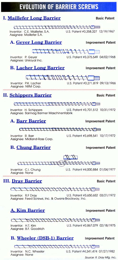
The nine historically significant barrier screw designs include three basic patents—Maillefer, Schippers, and Dray—and six improvement patents. Barrier feed-screw technology began with Maillefer's basic Swiss Patent and subsequent U.S. patent #3,358,327, filed in 1960 for a barrier flight that retains unmelted solids in a primary channel while melted resin goes downstream in an auxiliary channel.
Schippers' basic U.S. patent #3,701,512, filed in April 1971, has two different configurations. The first has parallel channels with the primary or entry channel reducing in depth while the auxiliary or melt channel (on the other side of the barrier flight) increases in depth. The second configuration adds distributive mixing by transposing the primary and the auxiliary flights. This causes the resin in the melt channel to mix with the resin on the trailing side of the primary channel.
The Dray basic U.S. patent #3,650,652, filed in 1970, increases the melting area with a longer lead at the end of the feed section. The longer lead allows the auxiliary channel to be included, while the width of the solids bed in the primary channel remains unchanged.
Improvement patents are patents that have precedent. They are intended to provide new technology that improves the prior art. Six improvement patents add new technology to these three basic designs. The first two basic European design patents were never used commercially in the U.S., but came here via improvement patents on them. Geyer's U.S patent #3,375,549, filed in 1961, and Lacher/NRM's U.S. patent #3,271,819, filed in '62, improve on Maillefer. Barr's U.S. patent #3,698,541, filed in 1971, and Chung's U.S. patent #4,000,884, filed in '75, improve on Schippers. Kim's U.S. patent #3,867,079, filed in '72, and Wheeler's U.S. patent #4,341,474, filed in '80, improve on Dray. (However, the Wheeler/DSB-1 barrier from Davis-Standard Corp. is more a hybrid—i.e., combining elements of Maillefer, Schippers, and Dray.)
Because the improvement patents have melting-channel configurations similar to those of the basic patents, only the basic designs need to be simulated. An exception is the Wheeler patent, which combines elements of all three basic patents in a melt channel with three different lead dimensions. Therefore four simulations were performed: the three basic designs and the Wheeler hybrid.
These four barrier sections were "unwrapped." The geometry of the barrier section with primary and auxiliary channels was simulated in a flat plane, as if it had been unwound off the screw and flattened out. The surface area of the melt channel was then calculated.
This method can be used to determine the melting capacity of any barrier-screw design. Total melting area is calculated as the surface area of the primary channel where solids contact the barrel wall and are melted mainly through surface friction. The size of this area determines melting capacity. This contact area in sq in. is converted into lb/hr of melting capacity using a simulation model for heat transfer.
As a control, a conventional non-barrier screw design with a square pitch was also evaluated for melting capacity. This channel section was unwrapped, and heat transfer between the melt pool and the solids bed was calculated.
Simulation result: The conventional non-barrier screw control shows a melting capability of 482 lb/hr.
Maillefer barrier family
Tadmor and Klein's original computer simulations modeled the break-up of the solids bed. In a conventional non-barrier screw, when the internal melt pressure is great enough, it penetrates the solids bed and disperses the remaining solids randomly into the metering section. This phenomenon mixes melted and unmelted plastic, reducing melt quality.
The Maillefer barrier, patented here in 1967, was the first barrier or melt-separation device used in a feed screw. It increased melting area relative to a conventional non-barrier design and eliminated the break-up of the solids bed, thus improving melt quality. The Maillefer design elongates the lead that starts on the pushing side of the primary flight and ends on the trailing flight. This flight becomes the barrier separating the solids bed from the melt and preventing solids from dispersing into the metering section.
The unwrapped channel section of the Maillefer barrier shows a flight with increased clearance that is initiated on the downstream side of the primary flight and has a lead longer than the primary-flight lead. After a number of turns, the barrier flight intersects the upstream side of the primary flight. It increases melting capacity without sacrificing extrudate quality. As melting progresses, melt is carried downstream in the auxiliary channel.
A pure Maillefer barrier screw was never available in the U.S. However, improvements on Maillefer, patented by Geyer and Lacher, are commonly used here. Geyer's patent, assigned to Uniroyal, and the Lacher patent, assigned to NRM Corp., vied with Maillefer for the U.S. barrier-patent rights. (Lacher was a patent attorney, not the designer of the screw.) The Geyer/Uniroyal claim won, and the Geyer patent became the first and dominant barrier design in the U.S. Uniroyal, however, made little use of it for plastics, but used it extensively for rubber extrusion. The NRM/Lacher version was named the "Plastiscrew" and was used as a downstream dispersive mixing section rather than a melt-separation device.
Because the Maillefer, Geyer, and Lacher designs are similar, an unwrapped channel section of the Maillefer design is representative of the melting-section dimensions of the Uniroyal/Geyer and NRM/Lacher designs as well—so the latter two are not analyzed separately.
Simulation result: By eliminating the solids-bed breakup, the Maillefer, Geyer, and Lacher designs gain additional melting area relative to the control non-barrier screw, increasing melting capacity to 539 lb/hr.
Deep vs. shallow channels
Schippers' barrier patent, as signed to Barmag Barmer Maschinenfabrik in Germany, was the first melt-separation design in which the primary channel gets shallower as the auxiliary channel gets deeper. Like Maillefer, it was also never marketed or widely used in the U.S. This design is known here primarily through Robert Barr's improvement patent on the Schippers design. Barr's design, assigned to Midland-Ross Corp., is used in many applications here.
Decreasing depth in the primary channel and increasing depth in the auxiliary channel—rather than a barrier flight that crosses the channel—allow for a greater melting area and therefore increase melting capacity over the Maillefer barrier.
Barr's is the first U.S. patent on a parallel-barrier screw. Based on the issue dates, it would be the basic patent and Schippers the improvement patent. However, Schippers' patent was filed first on April 7, 1971, while Barr filed Aug. 11, 1971. The issue dates were two weeks apart: Barr's on Oct. 17, 1972 and Schippers' on Oct. 31. Filing dates are normally accepted for precedence, as the issue date can be influenced by the examiner's schedule and communication between the examiner and patent attorneys.
The Chung patent is an improvement on the Barr barrier. Chung transposes the primary and barrier flights at the end of the barrier section for enhanced mixing. Because the Schippers, Barr, and Chung designs are all similar in the area of the primary melting channel, only the channel section of a Schippers barrier was unwrapped and analyzed for melting capacity.
Simulation result: The Schippers/Barr use of parallel channels increases the melting area over that of the tapered Maillefer barrier, achieving higher melting capacity of 697 lb/hr.
More melting capacity
The Dray barrier, assigned to Feed Screws Inc. and Owens-Brockway, was the first basic barrier patent developed in the U.S. It uses a longer lead at the end of the feed section to form the auxiliary channel for conveying the melt. That allows for the normal width of the primary channel containing the solids bed to remain the same after the lead change. The unwrapped channel section of the Dray barrier shows the separation of solids from melt with a long lead of unchanged width in the melting area.
The Kim barrier, assigned to B.F. Goodrich, improves on the Dray patent with a variable lead in the primary flight that continually widens the auxiliary channel. Like the Dray patent, the Kim design maintains a uniform primary melting-channel width. Unlike Dray, the primary channel is closed, which makes it a full, long-barrier design.
Simulation result: Dray and Kim's longer parallel lead increases the potential melting area, so melting capacity is also higher at 798 lb/hr.
The Wheeler barrier, also known as the Davis-Standard DSB-1 barrier screw, combines aspects of all three basic patents (Maillefer, Schippers, and Dray). The design, built by Davis-Standard Corp. of Pawcatuck, Conn., actually has three discernable leads in the barrier flight. These lead changes are the only difference between the Wheeler and the Maillefer barrier designs. The unwrapped channel section shows the initial lead change as in the Dray barrier. After approximately five turns, the lead then reduces until the last turn, where it elongates to close off the barrier section. The primary channel reduces in depth and the auxiliary channel increases in depth, as does the Schippers/Barr barrier design.
Simulation result: By reducing the widths of the melting channel, Wheeler's DSB-1 barrier actually reduces melting capability below that of either Schippers/Barr or Dray/Kim to 617 lb/hr.
The author thanks Chung and Wheeler for additional information provided for this article. The author also notes that all the barrier designs modeled here are based on patents or other public information. Subsequent changes in the designs may improve their melting capabilities.
Robert F. Dray, president of R. Dray Mfg. Inc. in Dallas, designs and manufactures extruder screws of all configurations and sizes up to 26 in. diam. and 40 ft long. As a consultant to Xaloy Inc., he designs barrier extrusion and injection screws. He invented and is the patent holder on the Dray barrier. The author may be contacted at (214) 368-5424 or rdraysr@aol.com


Related Content
Why Compression Ratio is Important
Compression ratios have been pretty much standardized over the years, based on what has typically worked before. But there are quite a few variables that must be considered in order to get the optimum performance from your screw.
Read More
Understanding the ‘Science’ of Color
And as with all sciences, there are fundamentals that must be considered to do color right. Here’s a helpful start.
Read More
How Polymer Melts in Single-Screw Extruders
Understanding how polymer melts in a single-screw extruder could help you optimize your screw design to eliminate defect-causing solid polymer fragments.
Read More
Troubleshooting Screw and Barrel Wear in Extrusion
Extruder screws and barrels will wear over time. If you are seeing a reduction in specific rate and higher discharge temperatures, wear is the likely culprit.
Read MoreRead Next

People 4.0 – How to Get Buy-In from Your Staff for Industry 4.0 Systems
Implementing a production monitoring system as the foundation of a ‘smart factory’ is about integrating people with new technology as much as it is about integrating machines and computers. Here are tips from a company that has gone through the process.
Read More
Advanced Recycling: Beyond Pyrolysis
Consumer-product brand owners increasingly see advanced chemical recycling as a necessary complement to mechanical recycling if they are to meet ambitious goals for a circular economy in the next decade. Dozens of technology providers are developing new technologies to overcome the limitations of existing pyrolysis methods and to commercialize various alternative approaches to chemical recycling of plastics.
Read More