How to Configure Your Twin-Screw Barrel Layout
In twin-screw compounding, most engineers recognize the benefits of being able to configure screw elements. Here’s what you need to know about sequencing barrel sections.


The design of the twin-screw extruder provides an advantage over other plastic processes. Full flexibility gives the process engineer the ability to configure the extruder to optimize the process and produce the best properties attainable. Most engineers recognize the benefits of being able to configure screws. The barrel sections can also be moved around to provide the optimum arrangement for the process at hand.
Processes such as single-screw extrusion and injection molding generally have fixed screw and barrel configurations. Once the process is designed, it is essentially fixed. Any changes require metal to be cut, resulting in potentially high costs for simple changes. For example, adding a vent to a single-screw extruder requires that the barrel be modified and a new screw fabricated. Each of these actions can be quite costly.


A twin-screw extruder, by contrast, is fully configurable. It can be viewed as a series of unit operations that can be arranged as needed to optimize the process. Segmented barrels and screws provide a flexibility not seen in other polymer processes. The proper sequencing of the barrel sections along with the corresponding screw elements can allow a broad range of process specialization.
Viewing the twin-screw extruder as a series of unit operations, the process engineer has the opportunity to address:
• Solids conveying;
• Melting of polymers;
• Customizable mixing of additives into the melt;
• Liquid injection;
• Downstream addition of additives;
• Venting (atmospheric and vacuum);
• Pumping;
• Heat Transfer;
• Chemical reaction, in the case of reactive extrusion.
Here, we will discuss the configuration of the barrel and how each barrel section can be used for various operations. In later articles, we will look at the screw configuration and the effectiveness of each element type on the various unit operations listed above.
Barrel Configuration
Most of us do not consider reconfiguring the barrel of an extruder as a practical option. However, the location of certain functionality can have a profound effect on the capability of the twin-screw extruder and effectiveness of the compounding operation. Fortunately, the twin-screw extruder offers many cost-effective options. Most manufacturers provide segmented twin-screw barrels consisting of individual sections that are four, five or six diameters long. Each barrel section is independently heated and cooled to provide precise barrel-temperature control.
Barrel layout can be arranged to optimize the process based on the compounding requirements.
Beginning with a bare machine consisting of only a motor, gearbox and frame, we can build the process section of the extruder as needed based on the compounds being made. For small-scale laboratory and pilot-plant lines, the barrel sections can be rearranged as necessary to optimize the process during development. Obviously, frequent changes would not be advisable for a large-scale twin-screw extruder due to the impracticality of moving around large, heavy barrel sections. In the same way, the screw is rarely changed on a large production line, while the screw configuration of a lab machine may be changed every day.
The barrel layout can be arranged to optimize the process based on the compounding requirements. Typically, once a layout is chosen it is not changed. The process engineer should keep in mind that changing the barrel layout is possible and can be considered if the unit operations needed are not in the preferred order. But, while possible, rearranging the barrel is not common.
Open Barrel Sections
A few barrel section designs provide the configurability that is unique to the twin-screw extruder. We will look at each of these barrel types in general and in more depth as we pair each barrel section with the appropriate screw configuration for the unit operation specific to that section of the extruder.
Every barrel section has a figure 8 pathway through which the screw shafts pass. An open barrel is a barrel that has an opening to allow for feeding or venting of volatiles. The same open barrel design can be used for both feeding and venting and can be placed at any location along the overall barrel.
Feeding: Obviously, material must be introduced into the extruder to start the process. The feed barrel is an open barrel section designed such that an opening exists at the top of the barrel through which material is fed.
The most common location for the feed barrel is in the Barrel 1 position — i.e., the first barrel in the process section. Pellets and free-flowing granules are metered with a feeder so that they drop into the extruder through the feed barrel directly on to the screws.
Powders with a low bulk density often present a challenge in that air is typically entrained with the falling powder. The escaping air blocks the flow of the light powder, reducing the ability of the powder to feed at the desired rate.
One option for feeding powders is to have two open barrel sections in the first two barrel positions of the extruder. In this setup, powders are fed to Barrel 2, allowing the entrained air to vent out of Barrel 1. This configuration is a known as a back-vent arrangement. The back vent provides a pathway for the air to exit the extruder without backing up the feed chute. As the air is removed, the powder can feed more efficiently.
Once the polymer and additives are fed to the extruder, these solids are conveyed to the melting zone where the polymer is melted and mixed with the additives. Additives can also be fed downstream of the melting zone using a side feeder.
The barrel section used for this operation is called a side-feed barrel. In addition to the figure 8 for the extruder screws, a second figure 8 opening in the side of the barrel allows the side stuffer to be connected directly to the extruder so that the additives are stuffed into the molten polymer. A standard open barrel is typically positioned just upstream of the side feeder as a vent to allow any entrained air to escape.
A more compact version of the side-feed barrel with an open vent is known as a back-vent combi-barrel (see Fig. 1). This has both a figure 8 to match a twin-screw feeder and a small vent opening on the top of the barrel section towards the upstream end of the barrel section for air to escape.
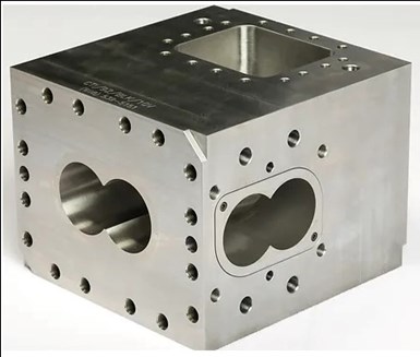
FIG 1 This combination barrel has a backward oriented atmospheric opening and side-feed port and offers a replaceable, highly abrasion-resistant CPM-10V powder-metallurgy steel liner in the main process channel and a replaceable wear-resistant side feed port. Barrels can be supplied with and without internal water cooling channels. (Photo: Composite Technologies Inc.)
Venting: The open barrel section can also be used for venting; volatile vapors that are generated during compounding must be vented before the polymer is forced through the die.
The most obvious location for a vent is toward the discharge end of the extruder. This vent is often connected to a vacuum pump to ensure all volatiles entrained in the polymer melt are removed prior to discharge through the die. Vapors or gasses remaining in the melt will result in poor pellet quality, including foaming and reduced bulk density, which may affect how well the pellets can be packaged.
My preference for an extruder that is at least 10 barrel sections long (L/D ≥40) is to place this vent two barrel sections upstream of the die. Quite often, if the extruder head pressure rises too high, molten polymer could back up in the vent. During a compounding run, the head pressure can vary, especially with a tight screen. If the viscosity of the polymer melt is low, the polymer will back up and flow out of the vent. Locating the vent two barrel sections before the discharge essentially eliminates this possibility, resulting in more stable operation.
Additional vents, both atmospheric and vacuum, can be added along the length of the extruder if high levels of volatiles are present, if a diluent is being injected to remove an undesired volatile, or if a large amount of liquid/vapor byproduct is being generated as the result of a reaction.
Closed Barrel Sections
The most common barrel section design is, of course, the closed barrel section (Fig. 2). This barrel section fully encases the polymer melt on all four sides of the extruder with only a figure 8 opening through the center for the screws.
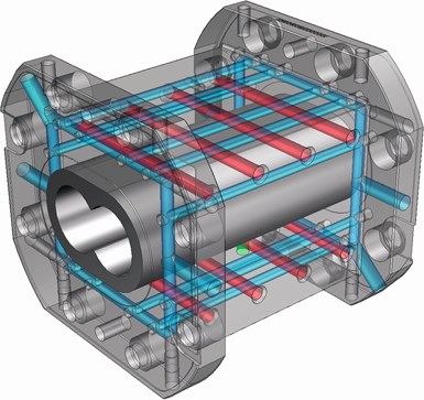
FIG 2 Closed barrel section showing heating (red) and cooling. (Photo: Leistritz)
Once the polymer and any other additives are fed completely into the extruder, the material is conveyed through the extruder, the polymer is melted, and all of the additives and polymers are mixed. Closed barrel sections provide temperature control on all sides of the extruder, whereas open barrels have fewer heaters and cooling channels.
Assembling the Extruder Barrel
Normally, the extruder will be assembled by the manufacturer with a barrel layout that matches the process configuration that is required. In most compounding systems, the extruder will have an open barrel in Barrel 1. This feeding section is followed by several closed barrels for conveying the solids, melting the polymers, and mixing the molten polymer and additives together. A combi-barrel may be located at Barrel 4 or 5 to allow side feeding of additives, followed by a few more closed barrels for continued mixing. The vacuum vent is located near the end of the extruder, followed by the last closed barrel before the die An example of an assembled barrel can be seen in Fig. 3.
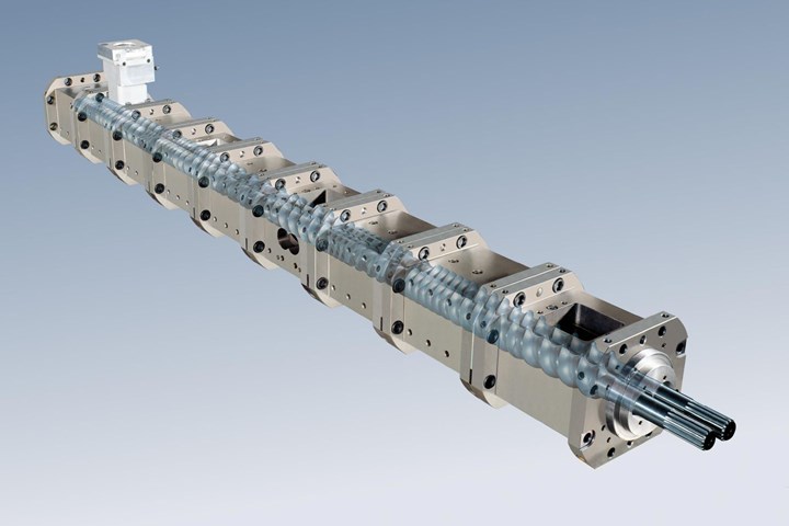
FIG 3 Assembled process section of twin-screw compounding extruder. (Photo: Leistritz)
The length of the extruder is typically expressed as the ratio of the length to the nominal screw diameter (L/D). In this way, scale-up becomes much easier in that a small extruder with a L/D of 40:1 can be scaled up to a much larger-diameter extruder also with a 40:1 L/D length.
In the coming months we will explore each of the unit operations discussed earlier, considering both the science and the art of configuring the twin-screw extruder for compounding and reactive extrusion.
About the Author: Kenneth W. Russell has more than 35 years’ experience working with polymer processing and resin companies. He has expertise in polyolefin polymerization, polymer compounding, reactive extrusion, and film and sheet extrusion. In 2014 he started Optimized Compounds LLC, providing consulting services in reactive extrusion, polymer compounding, new product development, process optimization and scale-up with clients worldwide. In 2021, he joined GEM Plastics, a manufacturer of HDPE sheet, providing process engineering, operator and technician training, and materials expertise. Contact: kwrcompounding@gmail.com.
Related Content

A Simpler Way to Calculate Shot Size vs. Barrel Capacity
Let’s take another look at this seemingly dull but oh-so-crucial topic.
Read More
PBT and PET Polyester: The Difference Crystallinity Makes
To properly understand the differences in performance between PET and PBT we need to compare apples to apples—the semi-crystalline forms of each polymer.
Read More
How to Set Barrel Zone Temps in Injection Molding
Start by picking a target melt temperature, and double-check data sheets for the resin supplier’s recommendations. Now for the rest...
Read More
Understanding Strain-Rate Sensitivity In Polymers
Material behavior is fundamentally determined by the equivalence of time and temperature. But that principle tends to be lost on processors and designers. Here’s some guidance.
Read MoreRead Next

People 4.0 – How to Get Buy-In from Your Staff for Industry 4.0 Systems
Implementing a production monitoring system as the foundation of a ‘smart factory’ is about integrating people with new technology as much as it is about integrating machines and computers. Here are tips from a company that has gone through the process.
Read More
How Polymer Melts in Single-Screw Extruders
Understanding how polymer melts in a single-screw extruder could help you optimize your screw design to eliminate defect-causing solid polymer fragments.
Read More
Lead the Conversation, Change the Conversation
Coverage of single-use plastics can be both misleading and demoralizing. Here are 10 tips for changing the perception of the plastics industry at your company and in your community.
Read More