
How to Manage Pressure Loss in Injection Molding
Achieving a process window wide enough to ensure consistent part quality depends on achieving sufficient pressure at end of fill.
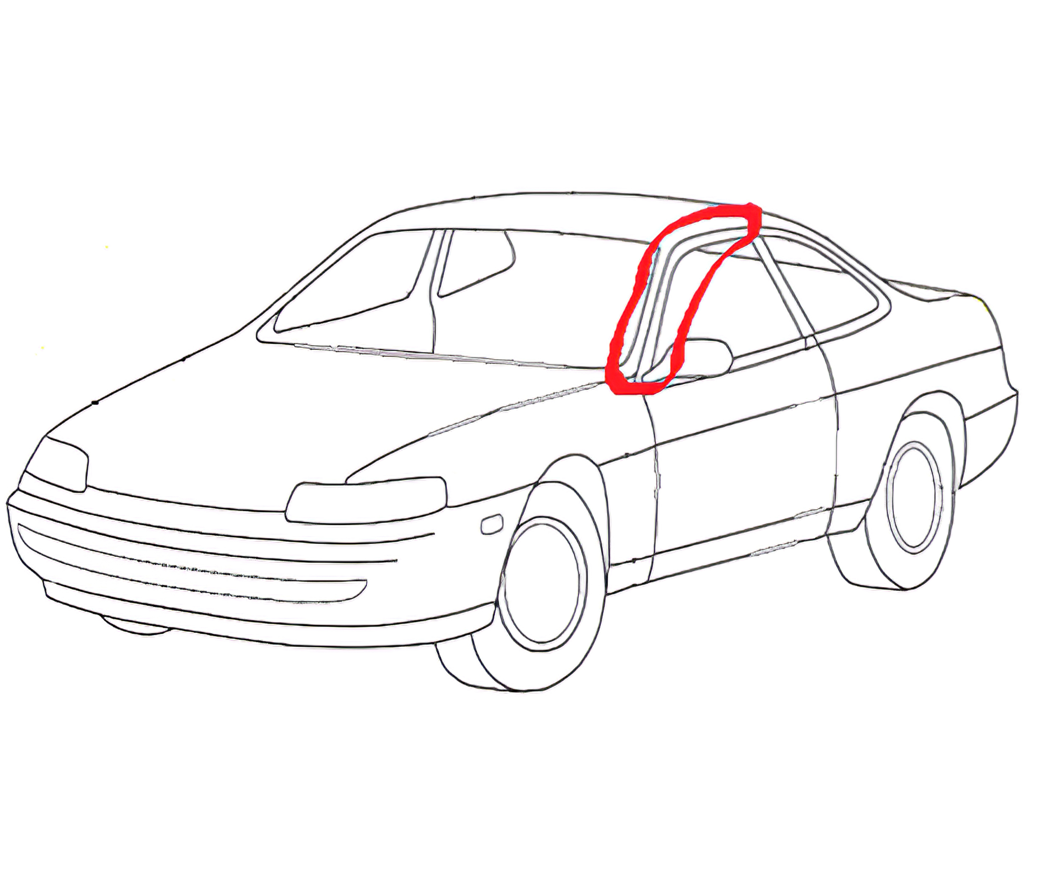
FIG 1 As an example, this automotive A-pillar is molded of a PC/ABS or PC/ASA alloys, so its viscosity is relatively high to start with. Good mold design, a capable molding machine, and a suitable process will be required to achieve a “safe” process window.
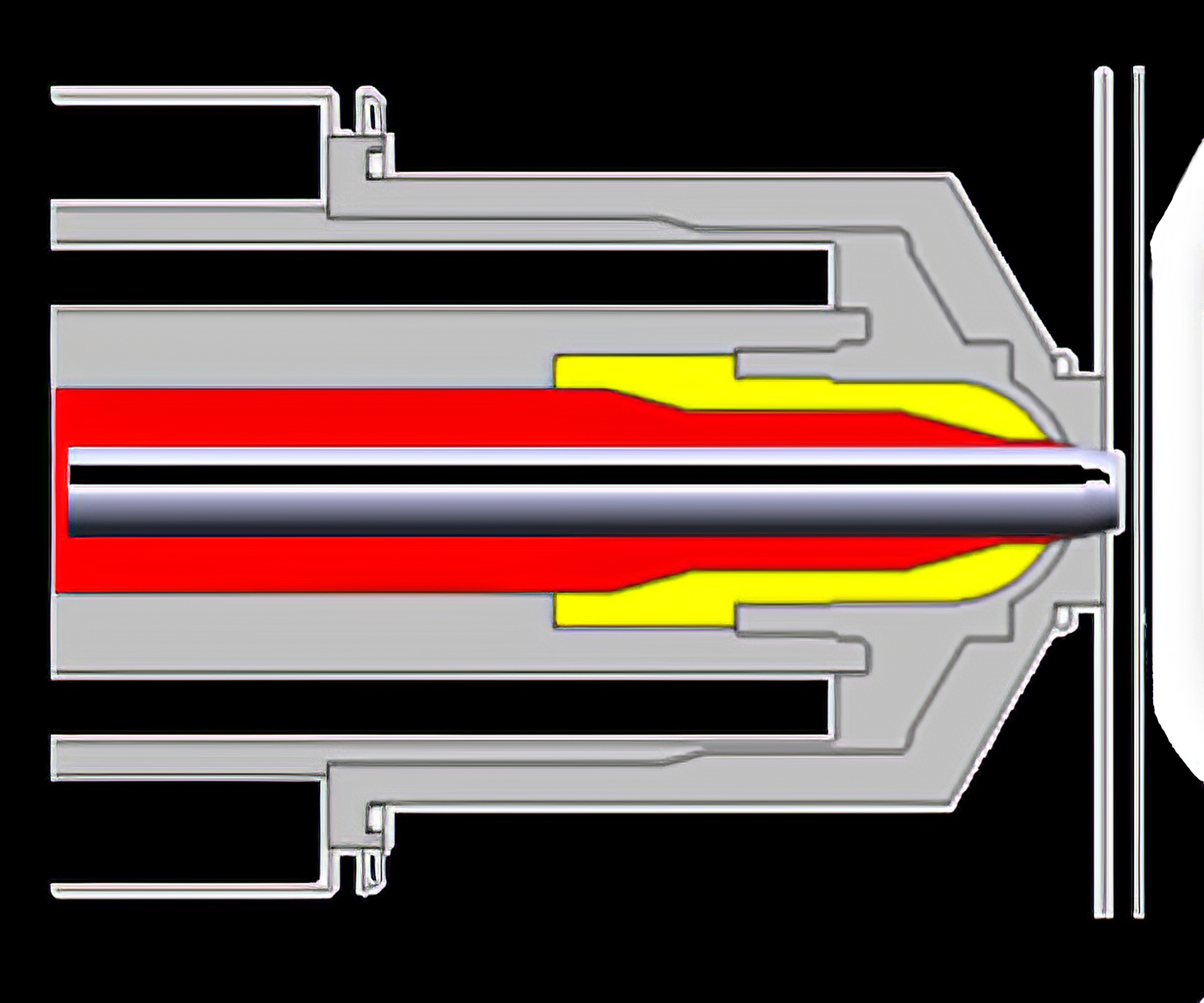
FIG 2 Sequential valve gating is one way to minimize the ratio of flow length to wall thickness in order to broaden the process window.
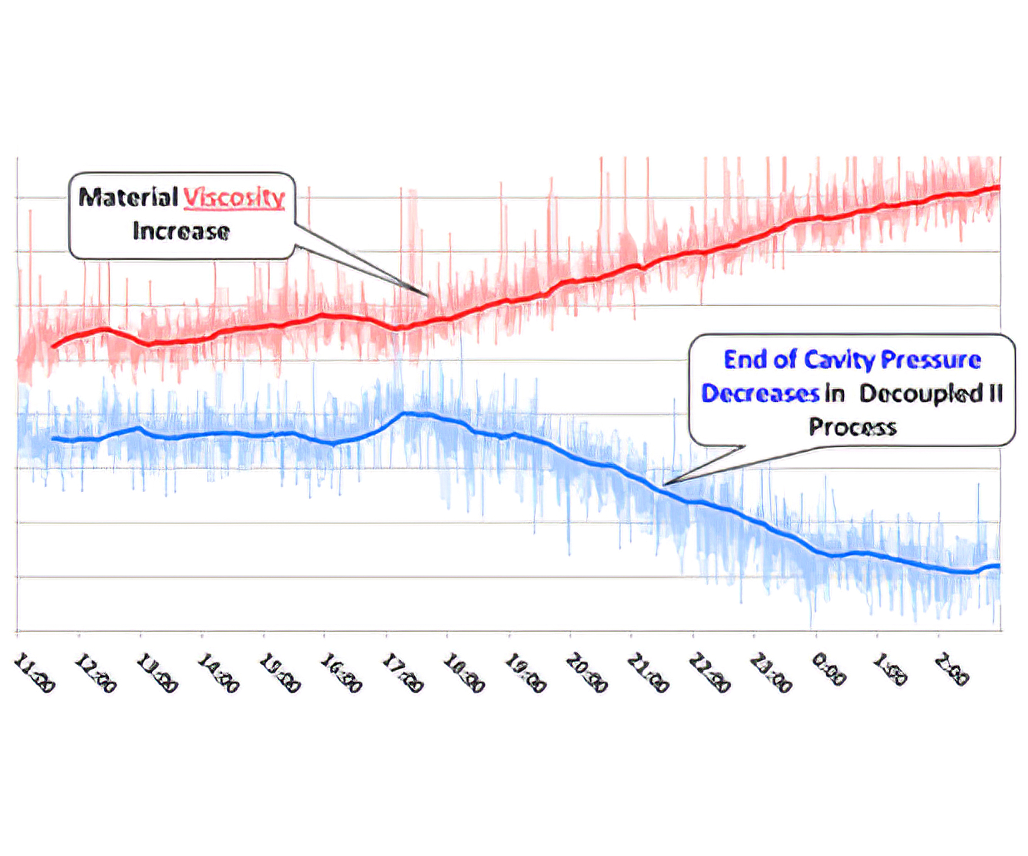
FIG 3 In a machine equipped with a hydraulic pressure sensor and a mold fitted with cavity-pressure sensors at the EOC, the eDart data from a 15-hr production run show how EOC pressure decreases in proportion to the increase in resin viscosity.


Ever encounter a part that has a process window thinner than a human hair? Managing the pressure loss in the molding process is complicated and influenced by many factors that are outside the control of the molder. We must evaluate each of the following areas to ensure that the molder has a wide process window.
Part Design
Ultimately, the success of molding starts at the OEM. No matter the environment or application, a design engineer must understand how the geometry influences the success of each manufacturing step along the way. The thickness of the part plays an important role in how difficult the molding process will be. Typically, injection molded parts will be between 0.040 and 0.250 in. thick.


Another factor that can drastically influence the molding success is how large the part is. To simplify this, we will use the overall length (OAL) of a part as an additional consideration. The OAL of injection molded parts can vary widely, just like thickness. In the medical industry, some parts could be as short as 0.250 in. In the automotive or appliance industry, the OAL could be 60 in.
Each part has its own challenges, but here we will focus on a thinner walled part with a large OAL. The example below is an automotive A-pillar (Fig. 1) for an automobile with a thickness of 0.080 in. and OAL of 55 in.
Material Selection
The first step of selecting a material is to evaluate the viscosity characteristics. Remember, viscosity is measuring the internal resistance to flow. Certain materials, like polycarbonates, will always have a high viscosity and will require higher injection pressure from the molding machine to create flow.
Next, the focus shifts to the Melt Flow Index (MFI) or Melt Flow Rate (MFR). The MFI or MFR will give an indication of the flowability of a material within a given type of resin. There can be a wide range of available flowability values for any given type of resin. When evaluating the MFI or MFR, it is imperative that a comparison be done only between the same types of resin (ABS to ABS, PC to PC, etc.).
If the material that is selected at the start of the project is naturally a high-viscosity resin, and has a low MFI or MFR, the risk of molding non-conformities increases drastically.
Now for a brief message about the incoming lots of resin. There will be variation and likely lots of it. The viscosity can deviate ±20%, depending on the quality of resin purchased. A typical virgin, wide-spec resin will fall into this category. If there are additives, such as color or glass, the amount of variation can be greater than ±20%. If regrind is added into the process, there can be viscosity shift of ±40%.
In a typical automotive application, the A-pillar is molded out of PC/ABS or PC/ASA. Given that PC/ABS is a medium-high to high-viscosity resin, the material selection increases the risks in consistently molding a high-quality product.
Mold Design
Now that we understand the size and material of the part to be molded, it’s advisable to evaluate the mold design. First, we must review the aspect ratio, which is a comparison of the flow length to wall thickness. Flow length starts at the gate and ends at the furthest point from the gate within the cavity. A high aspect ratio increases the probability of molding non-conformities.
When there are multiple gates required within the same part, it’s advised to balance the aspect ratio. The size of the gate plays a crucial role in how well the material will flow. It also influences the ability to pack out the part. If the gates are too small, the injection pressure during fill will be very high, and the ability to pack out the part will be negatively impacted.
In our example of the automotive A-pillar, the material must flow 55 in. through a 0.080-in.-thick wall, which yields an aspect ratio of 688:1. This ratio is extremely high if the part were to be single gated at one end. In this case, we would want multiple large gates strategically placed to reduce the aspect ratio. Also, since this part will likely be painted or chrome plated, knit lines are a concern. Given the cosmetic requirements, there is a good chance the mold would require sequential valve gates, shown in Fig. 2.
Molding Machine
The performance requirements of the molding machine are essential to the success of any process. Here are three factors to be evaluated when selecting a machine:
1. Ensure that the injection unit has the correct volume to avoid unmelted pellets or resin degradation.
2. It is critical to understand the volumetric flow rate. Thin-wall parts require higher volumetric flow rate to ensure the cavity is filled prior to the flow front freezing. Depending on the age of the molding machine, volumetric flow rates can range from 5 to 50 in.3/sec.
3. Consider the amount of plastic pressure the machine can produce in conjunction with volumetric flow rate. As the required volumetric flow rate increases, so does the plastic pressure required to achieve and maintain that desired flow rate. Taking into consideration the vintage of equipment, maximum injection pressure could be 20,000 to 45,000 psi.
Given what we know about the part geometry, material viscosity, and use of sequential valve gates in the mold for the A-pillar, the flow rate would likely be around 8 in.3/sec with peak plastic pressure during filling near 25,000 psi.
Processing
Over the years, RJG has learned that achieving a pressure at the end of cavity (EOC) of 3000 psi indicates that the steps leading up to the process have allowed for a wide process window. This is not to say that parts cannot be molded with less than 3000 psi at the EOC. They can, but the lower the pressure that can be obtained at the EOC, the risk of molding non-conformities increases exponentially.
In a Decoupled Molding II process—in which filling is separated from packing, if the viscosity of the material increases, the pressure at the EOC decreases, unless process changes are made. When pressure loss is greater than the validation pressure, some molding non-conformities that can be expected are undersized dimensions, warp, sinks, and short shots.
Figure 3 displays trend data from a 15-hr production run. The mold is equipped with cavity-pressure sensors at the EOC; the machine is equipped with a hydraulic pressure sensor to monitor shifts in viscosity; and the data is displayed on an eDart Summary Graph. Here the inverse correlation between viscosity and EOC peak pressure can be seen easily.
In the A-pillar application, we stated that the EOC has a peak of 3000 ppsi at PPAP. If the viscosity increases by 20%, which is likely to occur over the life of the program, it could result in an EOC peak of 1800 psi. If no process adjustments are made, we could expect parts that are undersized, warped, or have sinks over thick sections.
If a Decoupled Molding III process strategy is selected—in which cavity-pressure sensing is used to separate fill, pack, and hold—it can reduce the variation that is seen in the cavity when the material viscosity inevitably changes.
To recapitulate, when trying to manage pressure loss, we must first consider the thickness and size of the part. Second, evaluate the MFI of the material against the geometry in which it must flow. Not only do we have to consider the MFI at the onset of the project, but the potential variation of material over time. Next, consider the mold design to ensure the aspect ratio is correct. Also, determine the performance criteria the molding machine responsible for production. Finally, determine if the correct processing strategy was selected. If one of these critical areas is overlooked, it will be difficult to produce quality parts on a regular basis.
In short, if the part has a thin wall and long OAL and is running a high-viscosity, low-MFI resin and a high aspect ratio, the likelihood of achieving 3000 psi at the EOC is extremely low. A thorough evaluation of all the steps is required, as well as a better process-control method.
ABOUT THE AUTHOR
Jeremy Williams, consultant/trainer at RJG Inc. in Traverse City, Mich., has over 16 years of experience in the plastics industry serving the medical, automotive, furniture, and appliance industries. He previously worked as a principal engineer, taking projects from design concept to saleable products. Working with a wide variety of machines up to 9000 tons, processing a large catalog of resins in single-shot, two-shot and insert molding, he also gained knowledge of part design, simulation, mold design, robotics and secondary operations. Williams earned his Master Molder II certification in 2011 and became an RJG Certified Trainer in 2012. Contact: 231-947-3111; jeremy.williams@rjginc.com; rjginc.com.


Related Content

How to Set Barrel Zone Temps in Injection Molding
Start by picking a target melt temperature, and double-check data sheets for the resin supplier’s recommendations. Now for the rest...
Read More
Creating a Capable Process Using Process Capability
Know your Cp from your Cpk and how parts can meet dimensional specifications but still not be “capable.”
Read More
What is Backpressure and How Should We Calculate It?
Does using an intensification ratio to calculate backpressure result in an accurate reflection of what’s happening in the barrel? Newer machine technologies have us revisiting an old project with fresh eyes.
Read MoreRead Next

Lead the Conversation, Change the Conversation
Coverage of single-use plastics can be both misleading and demoralizing. Here are 10 tips for changing the perception of the plastics industry at your company and in your community.
Read More
Why (and What) You Need to Dry
Other than polyolefins, almost every other polymer exhibits some level of polarity and therefore can absorb a certain amount of moisture from the atmosphere. Here’s a look at some of these materials, and what needs to be done to dry them.
Read More
Advanced Recycling: Beyond Pyrolysis
Consumer-product brand owners increasingly see advanced chemical recycling as a necessary complement to mechanical recycling if they are to meet ambitious goals for a circular economy in the next decade. Dozens of technology providers are developing new technologies to overcome the limitations of existing pyrolysis methods and to commercialize various alternative approaches to chemical recycling of plastics.
Read More