Sink marks in injection molded plastic parts develop when material in the region of thick features such as ribs or bosses shrinks more than the material in the adjacent wall. The presence of such a feature creates an effectively thicker region that cools more slowly than neighboring regions. Differential rates of cooling result in a depression on the adjacent surface that is known as a sink mark.
This type of defect presents a major limitation to designing and molding plastic products, particularly in thin-wall applications such as TV bezels and display monitors. Parts for consumer electronics must be virtually free of sink marks, while toys often have sink marks clearly visible on their surface.
Formation of sink marks may be due to one or more factors, including the processing methods used, part geometry, material selection, and tooling design. Of these, part geometry and material selection are usually decided by the OEM and may not be easily changed.
However, there are several aspects of tooling design available to the toolmaker that can influence sink. Cooling-channel design, gate type, and gate size can have a wide variety of effects. For example, a small gate such as a tunnel gate freezes off much quicker than an edge gate. Premature gate freeze-off will reduce the available packing time in the cavity, which can increase the likelihood of sink marks.
For the molder, manipulating process conditions is a way to attack sink problems. Packing pressure and time significantly affect sinks. After a part is filled, additional material is packed into the cavity to reduce the effect of material shrinkage. A shorter packing phase will increase shrinkage, which will result in more or larger sink marks. While the molder can adjust packing conditions to improve sink marks, this approach on its own may not reduce sink marks to an acceptable level.
Other options are minor tooling modifications involving retrofittable components or process modifications such as gas assist or foaming.
Pins, gas, and foam
GE’s Polymer Process Development Center (PPDC) conducted a 12-month study to evaluate eight different approaches geared to reduce sink marks. These techniques represent some of the latest thinking on alternative approaches to sink-mark reduction. The alternative methods fall into one of two categories: either a material-displacement method or heat-removal technique. The material-displacement method looks to reduce sink by adding or removing material in an area where sink is likely to occur. The heat-removal method aims to pull heat away more quickly from an area where sink is likely to occur, thereby reducing the chance of differential cooling between thick and thin areas.
Types of Boss Pins
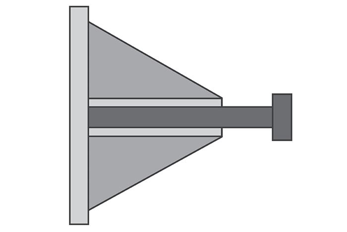
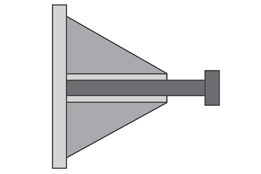
Standard boss pin: the baseline norm
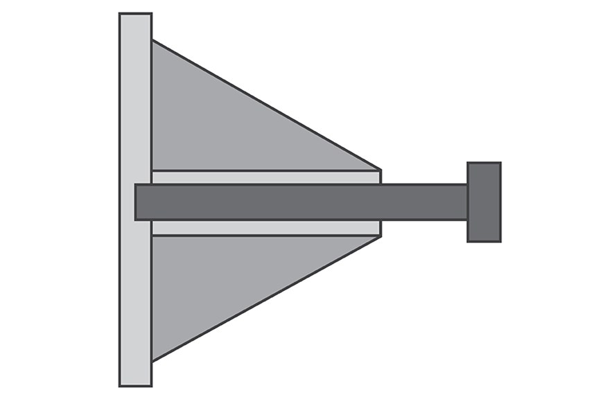
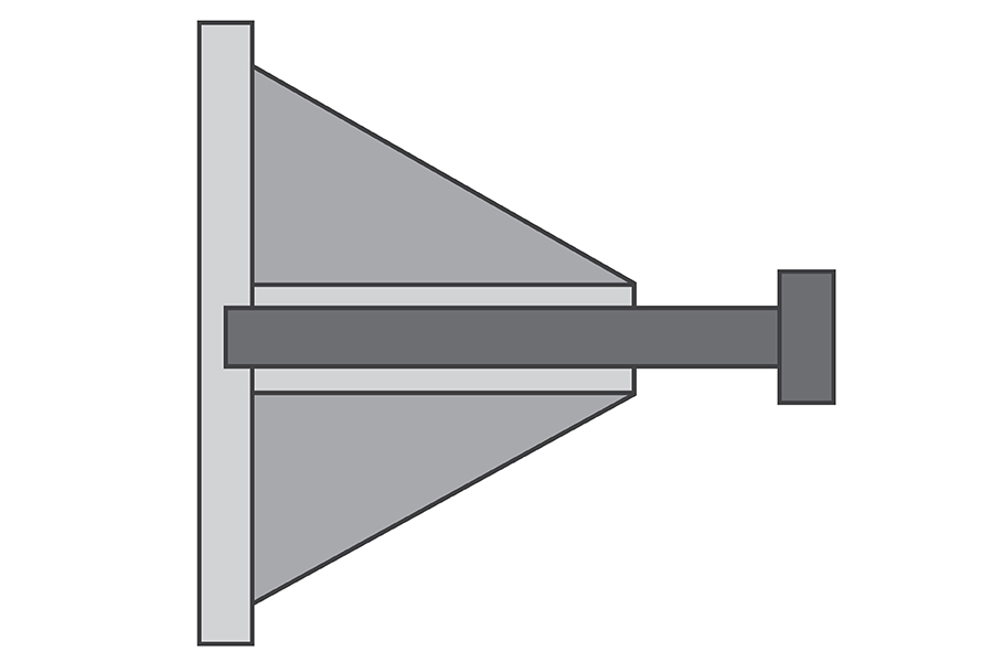
Protruding boss pin: low cost but material dependent
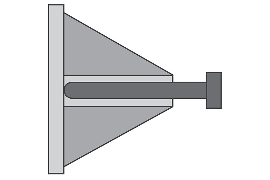
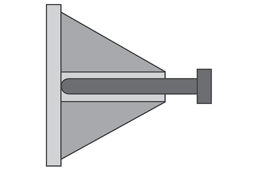
Radiused boss pin: Low cost but ineffective.
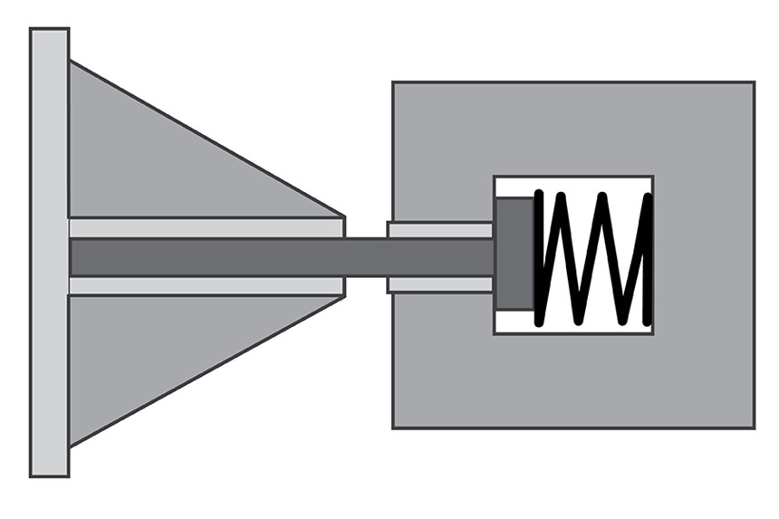
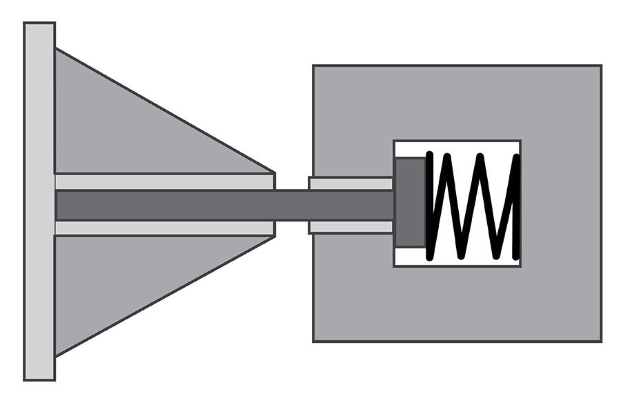
Spring-loaded boss pin: peak performer, but higher cost
Gas assist: Potential winner, but adds cost and complexity.
Be-Cu inserts: works with some resins; costly.
Be-Cu boss pin: Good performance
Active thermal boss pin: Weak performance. Hard to implement.
Five material-displacement methods were evaluated: a protruding boss pin, a radius on a boss pin, a spring-loaded boss pin, gas-assist molding, and chemical foaming. Three methods were evaluated for heat removal: a beryllium-copper boss pin, a beryllium copper insert, and a specially designed active thermal boss pin.
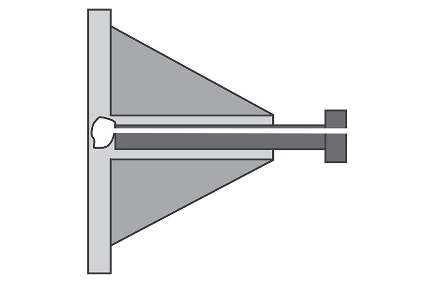
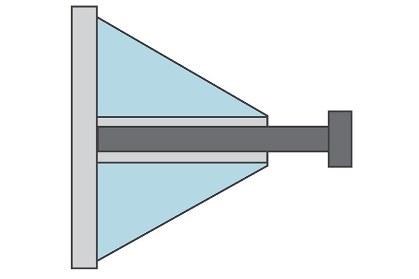
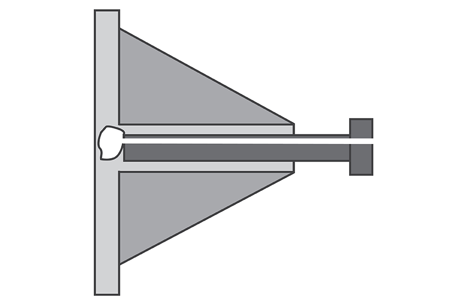
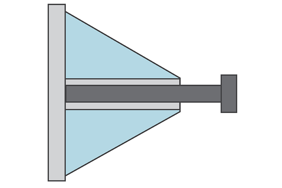
Eight alternative tooling approaches were tested for sink using this geometry. It has a 0.177 in. diam. boss with a 0.075 in. thick wall, and gussets that are 0.079 in. at the base.
We evaluated the magnitude of sink produced in a test part with a boss feature having attached gussets. All of these methods were compared against a standard tool-steel boss pin. The test tool produces a flat plaque with a nominal wall thickness of 2.5 mm (0.100 in.). The boss was 22.25 mm (0.875 in.) high and 4.5 mm (0.177 in.) in diam. It has 1.90 mm (0.075 in.) wall thickness and gussets that are 2 mm (0.079 in.) at their base.
Molding was performed at GE’s PPDC using a 350-ton, horizontal hydraulic toggle press. The tests used two materials common in consumer electronics applications where sink marks are problematic. They are GE’s PC/ABS, Cycoloy CU6800, and PPE/PS, Noryl PX5622. Both materials were processed at the midpoint of the range of conditions as suggested on the product data sheet. Since the resulting sink marks were minimal, the packing profile was intentionally adjusted downward so that the parts were under-packed to induce more sink. This allowed for easier measurement and comparison of the experimental methods.
Although sinks are usually evaluated subjectively "by eye,” these tests used a coordinate measuring machine to produce a quantitative measurement of the depth of sink.
What was tested
One standard technique that was tested was the protruding boss pin. The protruding boss pin is a standard pin that protrudes into the wall at the bottom of the boss, thereby reducing its thickness and offsetting the effect of the additional material in the boss. Two levels of pin protrusion—25% and 50% penetration into the wall opposite the boss—were used in the experiments.
We also tested a standard boss pin that has a radius on the end instead of a sharp edge. Although this method does not remove material from the boss area, it makes the transition between areas less abrupt.
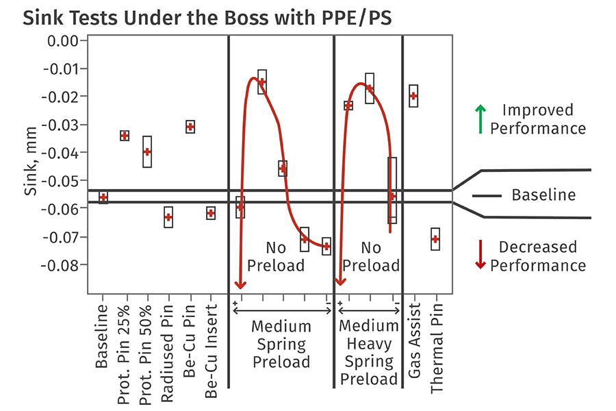
Another approach utilizes a spring between the boss pin and the ejector plate. Spring loading maintains pressure on the material under the boss as the part cools. The pressure will displace material in this region and compensate for shrinkage. Since results could be affected by the degree of initial preloading on the spring and the inherent "stiffness” of the spring, both of these parameters were evaluated as part of this experiment. Two springs of different stiffness were used and the pre-load was varied for each.
A chemical foaming agent was also evaluated since it has the benefit of not requiring any changes to the tool. The theory behind this method is that foaming will occur in the thicker areas where sink is most likely. This foaming may provide enough local pressure to prevent sinks. Only a small amount (0.25%) of blowing agent (Safoam RPC-40 from Reedy International Corp.) was used to prevent the formation of splay that would mar the part surface.
Gas-assist molding was tested by injecting nitrogen through a modified boss pin so that a bubble forms in the region under the pin where sink would normally occur. The desired effect is to remove material from that region and to pack the boss area via gas pressure within the bubble.
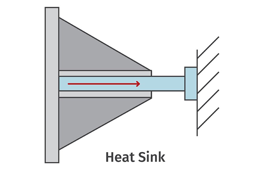
To test the effect of faster heat removal, a boss pin was constructed of beryllium-copper, a material more highly conductive than tool steel. This technique also requires that the back end of the boss pin be connected to a larger heat sink so that the heat can be removed entirely from the boss area.
A variation of this approach is to use a standard steel boss pin but install Be-Cu inserts around the boss area. This requires substantial modifications to the cavity side of the tool. A pocket is machined out in the area where the rib/boss structure is located. The rib and boss structure is then machined into a separate Be-Cu cavity insert, which is placed in the pocket. This highly conductive insert will draw heat from the entire region of the boss area and distribute it into the tool.
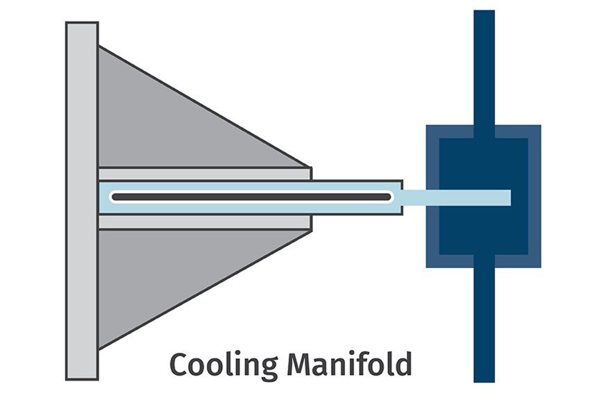
While the previous two methods use passive heat removal, an "active thermal boss pin" contains a fluid that carries heat away from the hot areas and delivers it to a cooling manifold.
What works best?
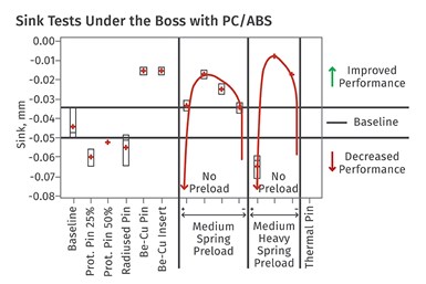
Five of the methods tested produced less sink than the baseline standard boss pin when PC/ABS was used. All of the heat-removal methods did well, while the only material-displacement technique that did much better than the standard pin was the spring-loaded boss pins, though the spring preload level significantly affected performance (see graph). Results with the gas-assist method are inconclusive: With this tool and material combination, melt freeze-off occurred too rapidly due to the thin walls and created difficulty in getting consistent gas penetration. The foaming tests were also inconclusive because visible splay on the part surface indicated that the amount of blowing agent should probably have been reduced before this technique could be compared fairly with the other methods.
When PPE/PS resin was used, the spring-loaded pins again did well. Three of the other material displacement approaches, including both of the protruding pins and the gas-assist technique outperformed the baseline results. On the heat-removal side, only the beryllium-copper pin performed better than the baseline.
Effectiveness of techniques for sink reduction vary with the material. The box or rectangle represents the range of data collected over 10 cycles. The red dot is the mean. Tests of spring-loaded boss pins used two springs of medium and heavy stiffness and different preload tension levels for each.
The radiused pin performed poorly with both materials. A surprise was the poor performance of the protruding pins with the PC/ABS material, since protruding pins have been recommended for nearly two decades. These tests indicate that they do not function equally well for all materials.
Overall, the most interesting results came from the spring-loaded pin. It improved sink by up to 50% for both materials when the spring was tuned properly. Spring stiffness seemed less important than the preload level. With too little preload, the plastic melt pushes the pin back too far, resulting in more material in the boss area and therefore more sink. When the spring has a high preload, it does not compress under the melt pressure and behaves much like the baseline/standard pin. The spring also showed surprising results when sink around the rib was measured. Even though this method was designed to minimize sink around the boss, there was a surprising improvement of the sink in the adjacent ribs when molding the PPE/PS material. It is possible that the compression of the pin effectively packed more material into the ribs, thereby reducing sink.
Molders should not discount the use of gas assist or a chemical blowing agent, despite the results shown here. In the case of gas-assist, the tooling was not optimized for that process. It could be expected to perform better in a larger part, due to its ability to cover a larger region than could a spring-loaded pin. And, as previously noted, the foaming formulation was not optimized in these experiments, either.
About the Author: Peter Zuber is a senior manager for SABIC. He has been in plastics since 1989, and has worked in various capacities for SABIC and GE Plastics for most of his career. He can be reached at linkedin.com/in/peterzuber.
Burger & Brown Engineering has released a new high-temperature low-flow indicator to monitor flow inside critical, restricted cooling paths such as those with bubblers or baffles.
New system automatically cleans mold-cooling lines—including conformal channels—removing rust and calcium, among other deposits, while simultaneously testing for leaks, measuring flow rate and applying rust inhibitor.
SeeScan adds conveying, drying, feeding and chilling technologies to improve quality — and enhance employee safety — in production of its underground/underwater inspection systems.
Understanding how polymer melts in a single-screw extruder could help you optimize your screw design to eliminate defect-causing solid polymer fragments.
Consumer-product brand owners increasingly see advanced chemical recycling as a necessary complement to mechanical recycling if they are to meet ambitious goals for a circular economy in the next decade. Dozens of technology providers are developing new technologies to overcome the limitations of existing pyrolysis methods and to commercialize various alternative approaches to chemical recycling of plastics.