
How to Select a Plastics Assembly Process
To make the proper choice, each application must be considered on its own. Each has its own particular characteristics and requirements.
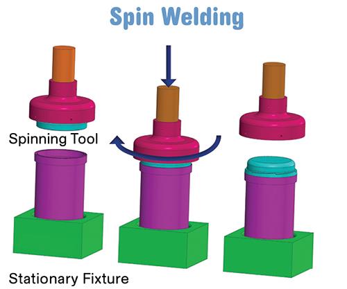
In spin welding, the weld is achieved by the friction created by rotating one part half against a fixed part half while under a clamp load.
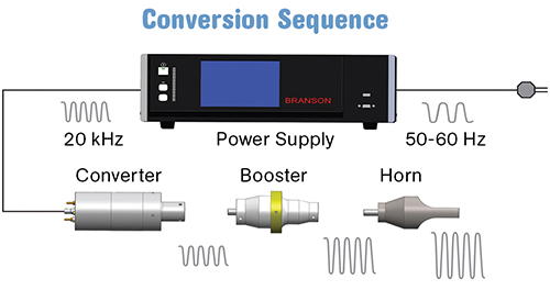
In an ultrasonic welder, the power supply, converter, booster and horn function together to create mechanical vibration.
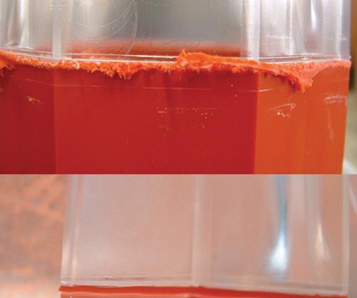
The photo on the top shows a standard vibration-welded bond of PC to PC/ABS, while the photo below shows the same part cleanly welded with Branson’s Clean Vibration Technology, which combines vibration and infrared welding.
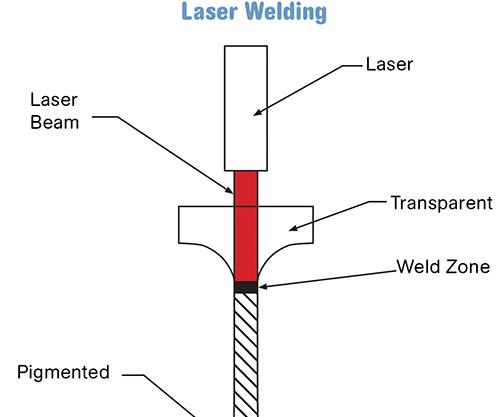
Illustrated here is the fundamental concept of the laser welding technique.


Making a decision on the best assembly process for your application can be daunting. There are several options from which to choose, ranging from mechanical fasteners and adhesives to friction and heat methods, each with distinct advantages. Moreover, every vendor in the business that you speak to seems to have the best solution.
To make the proper choice, each application must be considered on its own. Each has its own particular characteristics and requirements. Even if you have had success in the past with, let’s say, adhesive bonding, the application you are currently reviewing may be better suited to ultrasonic welding. To begin the process of selecting the proper assembly process, it is imperative that you define and list all of the properties and requirements, which include: component materials (make sure to include internal components, if any), part geometry, and end-user requirements.


Your best bet in selecting a process for your application is to go into the decision-making process with an open mind and be “process neutral.” Understand the advantages and limitations of each process available and work closely with equipment or system providers to develop a solution that works for your application.
Three main categories of methods are used in assembly of plastic components:
•Mechanical means include, but are not limited to, such options as snap fit, screws, rivets, and press fit. These methods are most often chosen when the product will need to be disassembled during its lifetime, such as a product with a removable battery pack. This method is also utilized in low-volume applications where the cost of capital equipment exceeds the cost of the consumable.
•Adhesives are most commonly used in applications where the materials are not compatible and you are looking for a permanent assembly solution. One example is a flexible PVC medical tube and a rigid plastic valve. There are many types of adhesives that can be used in a wide variety of applications. For optimum results, contact an adhesive manufacturer to determine the proper product for your application. You will need to consider the cost of the adhesive and keep in mind that this process typically requires some sort of dispensing machine and that the parts may need to be held in place while the adhesive solidifies.
•Friction and heat methods are typically utilized when you have materials that are compatible (see chart opposite) and you are looking for a permanent or tamper-proof seal. These methods, which are detailed below, do not use consumables. Therefore, the only cost incurred is the initial capital equipment investment and the electricity to run them. The rest of this article will distinguish the features of these processes.
FRICTION PROCESSES
Ultrasonic assembly is an extremely cost-effective and popular technique whose benefits include speed (most welds take less than a second), no consumables, minimal or no setup time, low cost of capital equipment, and easy integration into automation.
It utilizes a series of components—power supply, converter, booster, horn (or stack), and actuator—to deliver mechanical vibration and force to the parts. This generates heat at the interface of the mating parts, melting the plastic and creating a strong bond.
In these systems, the power supply, converter, booster, and horn function together to create mechanical vibration. The power supply takes standard electrical line voltage and converts it to an operating frequency (in this illustration—20 kHz). Power-supply frequencies are set but are available between 15 and 70 kHz. The most common frequencies are: 20, 30 and 40 kHz.
This electrical energy is sent through an RF (radio-frequency) cable to the converter. The converter utilizes piezoelectric ceramics to convert the electrical energy to mechanical vibrations at the operating frequency of the power supply. This mechanical vibration is either increased or decreased based on the configuration of the booster and horn. The proper degree of mechanical vibration, known as amplitude, is typically determined by an application engineer and is based on the materials being welded.
In a typical bench-type system, the actuator base and column can be removed, providing an excellent configuration for integrating into automation. The actuator is used to deliver the converter, booster, and horn to the parts being welded and applies force. Weld forces can range between 50 and 750 lb. The actuator also can have other components such as a linear encoder to measure weld distances.
The limitations of this process derive primarily from the materials being welded and the size of the parts. With an easy-to-weld material such as ABS, a part up to 10 x 10 in. could be welded with a 15-kHz welder. For a more difficult-to-weld material such as nylon, a part approximately 3.5 in. square or 3.5 in. diam. would be the largest that could be welded. Deep contours or reliefs in the horn may also limit its range.
Vibration welding is accomplished by holding one component in place while the mating part undergoes a reciprocating linear motion under force. The frequencies range between 100 and 240 Hz at an amplitude of 0.030 to 0.160 in. Machines are designed to return the mating parts to their original position for proper alignment. This method’s advantages are relatively short cycle time compared with other non-ultrasonic processes. Virtually all thermoplastics (crystalline, semi-crystalline as well as amorphous) can be successfully welded with this process. Large, complexly shaped parts can also be welded. Multiple parts can be welded in a single cycle.
Vibration welding is very tolerant with regard to a material’s heat history, additives, colorants, fillers, and even environmental contaminants such as dust, paint, and grease. Energy usage is low. A wide range of tooling (both in terms of size and type) can be put in the same machine rather than requiring a dedicated machine and tool set.
High-strength, hermetic seals are possible (99.9% of all vibration applications must be leak-tight in one way or another—i.e., to dust, air, water, blood, toner, ink, helium). “Corrective” melting is possible in the sense that energy can be continually imparted to the plastic parts to overcome even a high degree of part inconsistency.
Vibration welding does not adversely affect internal components such as printed circuit boards. Typical cycles range from 5 to 15 sec, depending on part size.
Limitations of vibration welding are mostly related to the ability of the part designer to incorporate the features required for the process. Because mechanical friction is used to create the weld, the parts must have relative motion between the mating parts of at least 0.070 in. peak to peak. Walls that are perpendicular to the vibration motion must be designed so that they do not flex during vibration. Depending on the size of the weld and the depth of melt, a certain amount of weld “flash” will be produced. If this weld flash must be hidden due to the aesthetic requirements of the finished part, a flash dam or flash trap can be incorporated into the part design.
Recent advancements have led to a hybrid design that incorporates vibration welding in combination with infrared technology. In this method, known as Clean Vibration Technology (CVT), the weld interfaces are precisely preheated with an infrared heat source and then are vibration welded together. This technique provides all of the advantages of vibration welding, but minimizes the flash and particulates that typically form in the standard process. Parts are loaded the same way as in the standard process, however, an infrared heat source is brought in to precisely heat the weld interface.
Once the infrared heat source is removed, the parts are vibration welded. Cycle times are usually extended to 25-40 sec.
Spin welding is a friction method for joining two thermoplastic parts together, forming a molecular bond. The weld is achieved by the friction created by rotating one part half against a fixed mating part half while under a clamped load. Once the rotation stops, the parts are held together for a short time to solidify the bond. Naturally, the joint between the two components to be welded must be circular. The smaller-mass half is usually located in the upper spinning portion, but exceptions can be made based on part geometry.
A typical spin welder consists of an actuator that contains the motor for rotation, either a pneumatic cylinder or electric motor to supply the weld force, and a controller that manages the actuator movement, rotation, and other weld parameters.
Spin welding has many advantages over other welding techniques, such as obtaining high-strength hermetic seals and relatively short weld times (1-2 sec with total cycle times in the 5-7 sec range.) Moreover, the process is not as material-specific as ultrasonic welding, so that most thermoplastics can be processed. You can also weld materials from different molding processes (i.e., injection molded parts to extruded or blow molded components) as long as melt-flow index and melt temperature are very similar. In this process, far-field welding can easily be achieved, which is another advantage over ultrasonics. Orientation between the mating parts is possible with the use of a servo system.
NON-FRICTION PROCESSES
Hot-plate welding has one major advantage: Virtually any part shape can be welded. As long as a heat insert can be designed to match the curvature of the part, it can be hot-plate welded. Another advantage is that the weld flash produced is solid and homogeneous. It will not break or flake off and particulates are not created, which is particularly desirable in markets such as medical devices and consumer parts. This process can also be used to “correctively” melt parts that are out of tolerance. Large, complexly shaped parts can be welded, and multiple parts can be welded in a single cycle.
In this straightforward process, the mating parts are loaded into holding fixtures and both are brought into contact with opposite faces of a heat platen, consisting of a heating element and two heat inserts. Once the parts reach the resin’s melt temperature, the heat platen is removed and the parts are brought together to form a bond or weld. Typical cycle times run in the range of 30 to 50 sec.
The limitations of hot-plate welding are largely related to cycle time. Energy consumption also is high relative to other welding processes. The tooling that touches the plastic parts (the heat inserts) are typically coated with PTFE as a release agent. PTFE is a wear item, so the heat inserts have to be recoated on a regular basis as part of a preventative-maintenance schedule.
Laser welding is a gentle and clean joining process that enables welding of complex geometries and materials that are difficult to bond with other techniques. A unique approach to laser welding is Simultaneous Through Transmission Infrared (STTIR) welding, which provides reliable and robust seals by allowing for collapse or displacement during the weld without generation of particulates.
Laser welding requires that one piece of the assembly is transmissible and one piece is absorbent in the wavelength of the laser. Also, the geometry of the assembly must allow for delivery of the laser light to the weld site.
The equipment typically consists of a laser light source in the 780-980 nm infrared range, with the energy directed to the component through fiber-optic bundles arranged around the perimeter to be welded. The laser output from each diode can be spread out over a small or large area depending on the power density required. The fiber bundles are manufactured with circular ferrules or other geometry on the output that allow for easy tooling design. A typical laser welder includes a power supply, controls, and cooling system, along with the actuator and laser banks. The system can be either benchtop mounted or easily incorporated into automation.
This technique’s advantages are wide ranging. No particulates or flash are created. This is ideal in many applications, but has a huge advantage in medical, automotive, and electronics assembly. Cycle times are relatively short—in the range of 5 to 7 sec. During the process, there is no relative motion between the two components being welded. They are held in place so alignment between the two components is maintained.
One key limitation is that one of the components must be transmissive to the laser light and the other must absorb the laser energy. Ideally, the first would be a clear part and the other containing carbon black pigment. The part transmitting the light must be transparent to the laser, but there are many colored pigments that transmit laser light while appearing pigmented to the human eye. There are also pigments other than carbon black that will absorb the laser light to create welds. To be sure your combination of colors and pigments will work properly, you will need to consult with equipment providers.
Thermal processing is a plastics joining technique that utilizes a heated tip in direct contact with the plastic to soften and reform it into a desired shape. When used to install inserts or other metal components, the tip contacts the metal part, transferring the heat through the part into the plastic and then driving it into the plastic. Thermal processing is more closely associated with staking and inserting but can be used for a number of applications, including swaging; filter, film, and foil welding; and date stamping, to name a few.
One advantage, in general, is that the range of suitable plastics is wider for thermal than for ultrasonic assembly. Thermal processing is also well suited to simultaneously staking and inserting large numbers of parts without a large increase in cycle time. It is a quiet process and does not generate as much particulate as other processes. Parts with delicate components such as PCBs that could be damaged are another area where thermal processing is preferred due to its gentleness. Also, the jack-out/torque-out value of inserts is slightly higher with thermal processing than for ultrasonically installed inserts.
Limitations are in cycle time, as it is a relatively slow process. The transfer of heat from the tip and through the plastic is the controlling factor. This can be offset by machine design (rotaries, multi-up tooling) or when there are large number of points to stake/insert.
HOW TO ZERO IN ON THE RIGHT PROCESS
Although the many options available can make it difficult to determine which process is best for your application, here is a thought process that should work for a majority of applications:
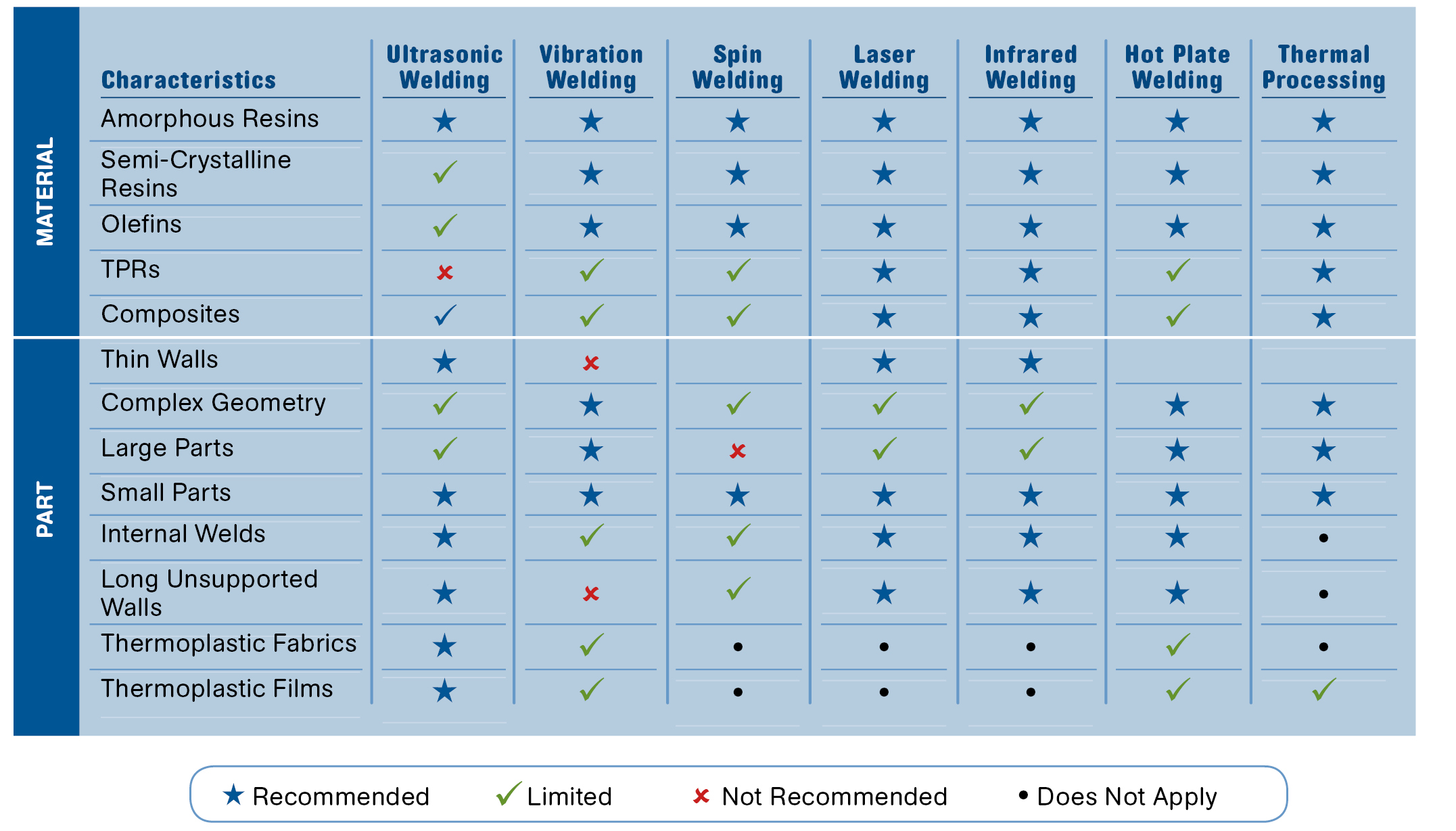
•The first consideration is material. Some materials, as shown in the chart, are more readily compatible with a given process. Polyolefins, for instance, are somewhat limited in ultrasonic welding, but are recommended for all of the other processes. Ultrasonics is not recommended for TPRs/TPEs and has limited capabilities in some applications, yet is recommended for others.
(Please keep in mind that all aspects of this chart are recommendations gathered through years of experience. and “limited” does not mean you can’t get excellent results. It is a guideline, not a hard-and-fast rule.)
•The second consideration is part geometry. Let’s start with the size of the part. One of the limitations of ultrasonics is the size of tooling. The lower the frequency (15 kHz), the larger the tool (approximate maximum, 10 x 10 in.). The higher the frequency (40 kHz) the smaller the tool (approximately 2.5 x 2.5 in.). If the partsare larger than these ranges, you will have to consider either multiple hits with ultrasonics or another assembly process.
•Delving further into part geometry, we come to the complexity of the part and weld profile. Some assembly processes can accommodate these features easily and others cannot.
•Wall thickness and internal walls must also be considered. Vibration welding, due to its linear reciprocating motion, has difficulty welding long unsupported walls, while other technologies do not have an issue with these part features.
•Production volumes cannot be overlooked. Some processes like ultrasonics, spin, and laser welding will process assemblies in seconds (or faster), while hot-plate welding may take 40-50 sec. In some instances you can weld multiple parts in a single cycle to improve throughput.
•Capital equipment cost should be the last consideration, though that may be easier to recommend than to put in practice. Keep in mind that if you select a process based on initial price, you may not have considered long-term processing costs such as scrap, downtime, and mold changes.


Related Content

Hot Wash Systems for Recycling Polyolefins
Herbold can configure wash plants for polyolefins that can produce high-quality, food-grade recyclates.
Read More
SD Polymers: 'One-Stop Solution for Mechanical Recycling'
‘Passionate’ recycler invests in people and technology to meet commitment to innovative, sustainable solutions for its processor customers.
Read More
Plastics Technology’s Most-Viewed Articles from 2022
Tips, new technologies, resin pricing, best practices and more piqued reader interest at Plastics Technology in 2022.
Read More
Can Plastic Recyclates be Welded Ultrasonically?
What is possible with ultrasound? Will the result with recycled plastics material actually be worse than with standard material? Do we have to adapt our technology?
Read MoreRead Next

Lead the Conversation, Change the Conversation
Coverage of single-use plastics can be both misleading and demoralizing. Here are 10 tips for changing the perception of the plastics industry at your company and in your community.
Read More
How Polymer Melts in Single-Screw Extruders
Understanding how polymer melts in a single-screw extruder could help you optimize your screw design to eliminate defect-causing solid polymer fragments.
Read More