How to Solve Uneven Clamping
Of the hundreds of variables involved in injection molding, clamping mechanisms and platens often get less attention than they deserve.
.jpg;width=70;height=70;mode=crop;format=webp)


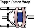
Massive as they are, platens “wrap” around the mold due to uneven application of clamp pressure. Toggles apply pressure in the corners, hydraulic clamps do so in the center.
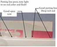
Pressure-sensitive paper shows much more than blueing agent would about uneven clamp pressure at the parting line that results in flash. (Pressurex paper from Sensor Products was used.)
Of the hundreds of variables involved in injection molding, clamping mechanisms and platens often get less attention than they deserve. Good clamp performance is critical to minimize cycle times, optimize part quality, and maintain process consistency. Alignment of the mold halves, platens, and clamping system is therefore critical.
When an alignment problem stems from the mold parting line, the platens, or the clamping mechanism and tiebars, the results can be unnecessary machine wear, mold damage, broken tiebars, mold flash, and scrap parts.


PARTING LINE ALIGNED?
One way to ensure proper mating of the tool halves at the parting line is simply by having a level molding machine and parallel platens. Leveling a machine requires three machinist levels. Start by getting all the adjustment screws on the leveling feet of the press to the same torque. Place one level across the tiebars or platen support near the fixed platen, another across the tiebars or platen support near the back end of the machine, and a third level lengthwise on a tiebar or platen support. One person goes to the appropriate leveling foot and raises or lowers it as directed by another person eyeing the levels.
Flash is a common part problem with a host of possible answers. If you have shorts and flash, you could have a mold or clamping alignment problem. This may not be the case if you are running a high-speed, thin-wall product—the problem may be simply not enough clamp force. To help establish whether flash stems from a mold or clamp alignment issue, check parting-line mating. In one typical check for uniform clamp pressure at the parting line, blueing agent applied to one mold half will transfer to the other if there is contact at the parting line, but it will not distinguish between low or high touch force. More detailed information can be obtained with pressure-indicating paper, which changes color relative to the amount of touch force. The shade of color change can be correlated with pressure.
Pressure-sensitive paper (such as Pressurex from Sensor Products) comes in a broad indicating range from 2 psi to 43,000 psi. I recommend a range of 7000 to 18,000 psi for parting-line troubleshooting.
To check for good parting-line touch force with pressure-sensitive paper, cover the parting line with the paper, close the mold up for 5 sec, then open and check for color uniformity on the paper. If you do not have uniform touch force on the parting line, the problem is either the mold or the clamp. If the machine is level and the platens are parallel, then the mold parting line is the source of misalignment. Die-height adjustment will only increase or decrease clamp force, it cannot adjust clamp-pressure uniformity, unless the platens are bowing.
CLAMP & TIEBAR ISSUES
Molders sometimes find that the clamp will not lock up completely after mold closing. The normal response is to check the parting line and look for flash or build-up there that may be preventing the mold from closing. If the clamp will not lock up after making parts for a relatively short time and there is nothing on the parting line preventing lockup, this is a hint of something more serious.
One place to start is to note the temperature of the mold and of the platen. If the mold is running hotter than 180 F, it could warm the platen. Check for platen expansion at the top tiebars (while warm) by measuring the distance between the top bars, then compare it to the distance between the bottom tiebars. Take your measurement near the stationary platen. Since the bottom of the fixed platen is secured to the frame of the machine, it is restricted to some extent from thermal expansion. However, the top of the fixed platen has no such restriction and will expand as the platen warms. This can create a situation where the distance between the top tiebars near the fixed platen is larger than that between the bottom tiebars. As the moving platen is pushed toward the fixed platen to close the mold, the now pushed-out upper tiebars can restrict the movement of the moving platen. If this is occurring, a telltale sign is galling or scratches on the sides of the tiebars. The solution is to keep the platens relatively cool.
Many processors feel that insulating the mold from the platen solves this problem, but it just extends the time before thermal differences between upper and lower platen appear. The insulator actually still conducts heat to the platen, though at a slower rate. Molders should put the insulator board between the clamping plates and the mold, not between the clamping plates and the platens.
Another way to prevent this problem is to actively cool the platens. Molders can gun-drill the clamping plates for cooling lines and control them to a moderate temperature. It is rare to see a machine with cooling lines in the platens, but if cooled, the platen will not thermally expand as much, and process consistency will be improved as the platens will be thermally stabilized during startups or shutdowns. Gun-drill the clamping plate and use a fluid temperature-control unit (TCU) to keep the platens at or below about 130 F.
Tiebars can also be thermally affected by hot air generated during processing. Since hot air rises, the top tiebars may get warmer than the bottom bars. Such a temperature difference may mean that the clamp won’t compress the parting line evenly. For example, if the tiebars are 10 ft long, and the upper tiebars are 15° F warmer than the bottom bars, the top bars would “grow” 0.012 in. longer than the bottom bars. This creates a difference in clamp force top to bottom. Mold cavities may flash due to the top tiebars being hotter and therefore longer than the bottom bars.
HOW MUCH FORCE?
It is important to know the clamp force required for a job and to use the smallest appropriate machine. Molders should find the minimum clamp force that also minimizes flash. Too much clamping force on a small mold causes the mold to bow in the middle. Less clamping force will provide more uniform pressure. An industry rule of thumb is 2 to 6 tons per square inch of projected area. Easy-flowing plastics should be in the lower range, while stiff-flowing resins like polycarbonate or acrylic are at the higher end of the range. If the nominal wall is thin or there is a long flow path, required tonnages go up dramatically.
It may be hard to believe, but platens—as massive as they are—can “wrap” around a mold, especially if too small a mold is mounted on a large platen. Molders should make sure that the mold occupies 70% or more of the distance between tiebars to avoid this.
Platen “wrapping” can occur regardless of whether the clamp force comes from a toggle or from hydraulic cylinders. It occurs also with tiebarless presses and with hydromechanical, two-platen types in which hydraulic cylinders pull, rather than push, the platens together. For toggle clamps, the moving platen “feels” the clamping force in the corners, while for a fully hydraulic clamp, the force is applied in the middle of the moving platen.
You can see evidence of platen wrap when the mold is removed from the press and there is loose rust on the platen where the mold hung. This rust lies on the surface of the platen, not pounded into it as would be expected. If a mold has been in a press for more than a few hours, when it is removed you see only the outline of the mold.
Platen bowing can lead to cracked cavities due to metal fatigue. The problem is so prevalent that special “negative-pressure” TCUs can be used that suck coolant through the mold rather than push coolant through it. This keeps water from getting into the cracked cavity and ruining the part.
Another solution taken by some mold builders is to cut off the corners of a mold in an attempt to get the clamp force more evenly distributed across the mold face. This provides a bit better clamp pressure uniformity, as the corners are not the pressure points. Also, mold builders will “pre-stress” the mold with center support pillars that are longer or taller than side pillars by 0.002 to 0.004 in. The mold will bow slightly prior to clamp-up and injection.
About The Author
John W. Bozzelli has taught seminars on plastics design and processing for more than 30 years. He has extensive experience in polymer development and processing from more than 20 years with Dow Plastics. He is the founder of Injection Molding Solutions/Scientific Molding in Midland, Mich., a provider of in-plant training, troubleshooting, and consulting services. Tel: (998) 832-2424 or e-mail: John@scientificmolding.com
Related Content

Best Methods of Molding Undercuts
Producing plastics parts with undercuts presents distinct challenges for molders.
Read More
What to Do About Weak Weld Lines
Weld or knit lines are perhaps the most common and difficult injection molding defect to eliminate.
Read More
Understanding the ‘Science’ of Color
And as with all sciences, there are fundamentals that must be considered to do color right. Here’s a helpful start.
Read More
Know Your Options in Injection Machine Nozzles
Improvements in nozzle design in recent years overcome some of the limitations of previous filter, mixing, and shut-off nozzles.
Read MoreRead Next

Processor Turns to AI to Help Keep Machines Humming
At captive processor McConkey, a new generation of artificial intelligence models, highlighted by ChatGPT, is helping it wade through the shortage of skilled labor and keep its production lines churning out good parts.
Read More
How Polymer Melts in Single-Screw Extruders
Understanding how polymer melts in a single-screw extruder could help you optimize your screw design to eliminate defect-causing solid polymer fragments.
Read More
Understanding Melting in Single-Screw Extruders
You can better visualize the melting process by “flipping” the observation point so that the barrel appears to be turning clockwise around a stationary screw.
Read More