
In-Mold Labeling: Electrostatics Are the Way to Go
Applying a static charge to hold the label in the injection mold eliminates the need for vacuum ports that addsignificantly to the cost of making and maintaining the tool.


In the U.S., IML is used on toys, office supplies, power tools, and lawn mowers. Interest is growing for food packaging, on which IML is used in Europe. (Photo: Plastics Technology)
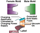
Fig. 1—Mandrel with suction cups embedded in antistatic foam (left) rotates to pick up label from magazine while static charge is applied to the label. Mandrel inserts label into mold (right), where label is attracted to grounded tool. Vacuum is shut off, and mandrel retracts.
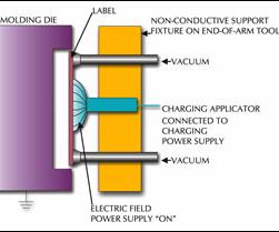
Fig. 2.—The conventional IML method is to mount the label-charging applicator on the robot end-of-arm tool.
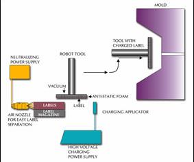
Fig. 3—Simplified electrostatic IML approach for flat containers places the remote charging applicator in a fixed position where the robot passes it on the way to the mold.
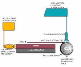
Fig. 4—Simplified electrostatic IML for round containers requires rotating the mandrel holding the label to get overall charge coverage. Antistatic foam provides good support and easy release of label.
Applying a static charge to hold the label in the injection mold eliminates the need for vacuum ports that addsignificantly to the cost of making and maintaining the tool. While the in-mold labeling (IML) pro cess for injection molding has been around for over 25 years, interest has snowballed in the last two. Applying the label during molding eliminates a secondary step for pad or screen printing or label application, as well as corona or flame treating. More important, the end result is permanent. This makes it especially attractive for product-liability and instructional information, as well as UPC codes, logos, and decoration. IML is also cleaner and more sanitary because there’s less handling of the product. And recyclability is enhanced if the label material is the same as that of the molded part.
Although there are numerous ins and outs of IML technology, one of the most important considerations is how the label is held in place in the injection molding tool. In many applications, electrostatics offers a reliable and cost-effective alternative to the use of vacuum for holding the label in its proper location in the die. This approach can provide distinct benefits to the molder as well as the molder’s customer and the end user.


Holding with vacuum
A label can be held in the desired location in the mold by specially designed and machined vacuum ports. The sequence is as follows: A robot picks up the label from a magazine, places it in the proper position in the die, the vacuum is turned on, and the mold is shot.
Designing and machining the die to incorporate vacuum can add significant cost to the tooling. Next, the label must be substantial enough to prevent it from being sucked into the vacuum ports, causing a deformed image or “pimples” on the surface of the finished product. Vacuum passages in the molding die may also result in non-uniform die temperatures.
In addition, it is very important that the robot does not miss the label. Injecting the mold without a label in place can result in very time-consuming and costly downtime to remove the die and clean out all the vacuum ports and passages. To prevent this requires a means of detecting the vacuum and stopping injection of the polymer into the die.
The use of vacuum appears to be most advantageous when the shape of the molded product requires complex preformed labels or when the molded part and/or label is required to have a textured surface.
Holding with electrostatics
Use of electrostatics in the IML process offers cost and reliability benefits by eliminating the need for vacuum in the die. When a static charge is placed on a label of suitable material and construction, the label will be attracted electrostatically to the grounded metal surface of the die and may stick with excellent adhesion for up to several minutes.
In the electrostatic process, the robot picks up the label from the magazine with suction. A high static charge is placed on the label either as the EOAT with the label approaches the press or as the label approaches the die surface. The robot positions the label, releases the vacuum, and the label is transferred to the surface of the die. No vacuum in the die nor adhesive on the label is needed (see Fig 1).
Although some injection molders have attempted to charge the label and place it in the die manually, experience has shown this to be a labor-intensive and unreliable approach that also slows down the press cycle.
Using electrostatics to their full advantage requires the following components:
- A robot with a suitably designed end-of-arm tool (EOAT).
- A label magazine.
- A high-voltage DC charging power supply with 30-kV adjustable output capability.
- A label of proper material and construction to accept and maintain a static charge.
Standard charging method
Although incorporating the charging applicator(s) on the EOAT offers a high degree of reliability and repeatability, it presents somewhat of a challenge for the designer of the EOAT. The applicator may be a straight static-charging bar of some specified length having a row of emitter pins, or it may be a series of individual emitter modules. The style and number of applicators required depends upon the size and shape of the label and contours of the die surface where the label is to be placed. Therefore, each EOAT will require its own unique charging applicator set-up.
While the label is being held by the suction cups on the EOAT, the charging applicators are located directly behind the label (Fig. 2). The emitter pins typically face the back of the label from a distance of about 1 in. When the robot places the label against the die surface, the charging power supply is turned on for a period of about 0.5 to 2 sec. This places a static charge on the label and the label instantly adheres to the grounded metal die. The vacuum is turned off and the robot extracts the EOAT from the press.
When designing the EOAT to incorporate the charging applicator, a few guidelines should be considered to assure optimum label charging. For example, if the emitters are to be placed 1 in. behind the label, any metal parts of the EOAT should be grounded and at least 1.5 in. away from the emitters. Metal any closer than this will attract some of the electric field from the charging applicator, resulting in less charge on the label.
If individual emitters are to be mounted on a plate that also holds the vacuum suckers, the plate must be made of a nonconductive material such as polyethylene, PTFE, PVC, UHMW-PE, or acrylic. Any component of the EOAT close to the charging applicator should be made of a nonconductive material, if that can be done without sacrificing strength and structural integrity. Any component that is electrically conductive (metal) must be grounded.
Two types of charging applicator are available: current-limited and non-current-limited. Current-limited types come in the straight static-bar style or as individual emitter modules. They contain a resistor that is in series with the high-voltage supply. The advantage is that this applicator will not “hard arc” if it gets too close to the metal and offers a high degree of safety if personnel should accidentally touch it while energized.
A hard arc is a high-current arc-over, usually seen as a distinct bright white or yellow spark from the high-voltage emitter of the charging applicator to a conductive surface, such as the cavity of the metal mold. This can occur when a non-current-limited applicator is positioned too close to the mold or when its operating voltage is set too high. The high-voltage energy from the applicator’s emitter breaks down the insulation properties of the air between the emitter and the grounded metal surface of the mold, causing the arc. Such arcs can cause pits in the die surface and radio-frequency interference (RFI) that may affect microprocessor controls of the robot or the press.
In contrast, the current-limited applicator’s resistor limits the amount of current that can be drawn from the emitter, thereby preventing a high-voltage arc.
Some of the newer electrostatic power supplies contain arc-sensing circuitry designed to protect the solid-state components of the power supply when it is used with a non-current-limited applicator. If excessive current draw is sensed by the power supply, its control circuitry immediately goes into arc-protection shutdown mode, which turns off the high-voltage output to protect the power supply’s sensitive electronics. When this happens, static charging is interrupted. That can be a common and troublesome occurrence when non-current-limited applicators are used.
As another safety precaution, the high-voltage cable from the charging applicators to the power supply must be supported along the robot arm with sufficient slack to allow for the required movement with the least physical stress on the cable. These cables should be inspected on a weekly basis and replaced if fracture, abrasion, or weakness of the cable is detected.
Simple charging method
Use of a remote-mounted charging applicator is a simplified way to apply a charge. It requires little modification of the EOAT, is relatively easy to set up, and can satisfy the requirements of many different sizes and shapes of labels with the same charging applicator.
This means of charging will work for most film labels that are applied to relatively flat mold surfaces.
In this charging process, the robot picks up the label at the magazine, orients the label, and passes it by the charging bar. The ground reference surface behind the label attracts the electric field from the charging bar and the label becomes charged. The robot places the label in position against the surface of the molding die, releases the vacuum to the suction cups, and the label stays in place on the surface of the die.
With this approach, a charging applicator bar is mounted on a permanent fixture between the molding press and the label magazine. The charging power supply can be turned on manually and left on during the duration of the run, or it can be turned on and off remotely by the robot’s PLC.
In some cases, the label may not release readily from the suction cups and may skew slightly due to mutual electrostatic attraction caused by static charges building on the surfaces of the suction cups. If this occurs, a static neutralizer bar can be mounted in the robot’s path between the charging bar and the label magazine. Each time the robot returns to pick up a new label, the suction cups will be neutralized. Smaller diameter suction cups will decrease the charged surface area, which may help minimize the problem.
The fixture on the EOAT requires a grounded conductor such as a metal plate. The conductive surface should be at least as large as the label and mounted 0.25 to 0.5 in. directly behind the label. The suction cups should have the minimum diameter necessary to provide sufficient holding power to prevent the label from slipping and attracting to the grounded conductive surface of the fixture.
All conductive components of the robot fixture must be grounded and should have radiused edges and corners. There should be no sharp edges or corners within 1 in. of the label.
Another version of the simplified method provides even better physical support and uniform transfer of the label from the EOAT to the die. This process functions the same as described above but requires the addition of a piece of antistatic foam mat bonded to the metal ground reference plate on the EOAT. This material should have a thickness of approximately 0.375 in. and should have an electrical surface and volume resistivity of approximately 109 to 1010 ohms. This type of material is available from most static-control distributors who service the circuit-board assembly industry. Most of these materials are manufactured with an embossed textured surface and may require sanding to achieve a smooth, uniform surface. Sanding the surface also enhances charging of the label.
The suction cups are incorporated into the foam material and should be flush with the surface (Fig. 3). Since the foam pad has a high electrical resistance compared with the grounded metal mold surface, the charged label has a greater affinity for the mold and transfers from the foam pad to the mold when the vacuum is switched off. Figure 4 is an example of how this may be accomplished for 360° labels on round containers.
Key label properties
The physical and electrical characteristics of the label are extremely important to the reliability of using static charges to adhere the label to the mold. The surface of the label that is to contact the mold cavity must be a good insulator to accept and maintain the static charge. Ideally, this surface should have a resistivity of 1012 ohms/sq or greater. The higher the resistivity, the better the label will accept the charge without bleeding the charge to ground when it contacts the metal mold cavity. If the charge is not maintained when in contact with the die, adhesion is lost and the label slips from the intended position. Measurement of the label’s resistivity can be performed using a commercially available surface resistivity meter.
If conductive inks, coatings, or foil laminations are used, they must be on the back side of the label, opposite the surface that is to contact the mold. In such a case, the best method for charging the label is with the charging applicator external to the press (the simplified charging method) and the conductive surface of the label against the vacuum ports on the EOAT. If the charging applicator is mounted on the EOAT behind the label, the high-voltage field cannot penetrate the conductive layer and sufficient charge will not be applied to the surface that is to contact the mold cavity.
A word of caution: A charged foil or conductive layer will most likely discharge in the form of an arc as it approaches the mold surface. A result of this arcing is RFI, which may cause problems with microprocessor controls, especially if unshielded sensors or cables are nearby. Ongoing arcing over a long period of time may also produce pits on the die cavity.
Label properties such as thickness, curl, and surface texture also affect adhesion. For example, a relatively thick label that may have some curl due to an asymmetrical laminated structure or improper storage may break loose from a flat die surface if the electrostatic forces are unable to overcome the physical forces causing the label to curl. Similarly, preformed labels may be required for compatibility with contoured die surfaces.
A textured label or die surface can also result in poor adhesion due to the reduction in intimate surface contact between the label and die surface.
A relatively thin, non-textured label with good dielectric properties on a non-textured die surface will produce the best adhesion. However, there are still other important adhesion factors to consider, such as molding temperature, polymer compatibility with the label, gate location, and material flow when the die is injected. For all these reasons, much time and frustration can be eliminated by consulting a label supplier with IML experience.


Related Content

Stratasys to Acquire Covestro’s Additive Manufacturing Materials Business
This acquisition will result in Stratasys having an expanded portfolio of differentiated materials in stereolithography, DLP, and powders.
Read More
Automation in Thermoforming on the Rise
Equipment suppliers’ latest innovations exemplify this trend driven by factors such as labor shortages, higher-speed thermoformers and tighter quality control.
Read More
Plastics Technology’s Most-Viewed Articles from 2022
Tips, new technologies, resin pricing, best practices and more piqued reader interest at Plastics Technology in 2022.
Read More
S&B Selected as Contractor for New Hope Energy Advanced Plastics Recycling Unit
New Hope Energy and Total Energies collaboration for an advanced plastics recycling unit gains momentum.
Read MoreRead Next

Troubleshooting Screw and Barrel Wear in Extrusion
Extruder screws and barrels will wear over time. If you are seeing a reduction in specific rate and higher discharge temperatures, wear is the likely culprit.
Read More
Advanced Recycling: Beyond Pyrolysis
Consumer-product brand owners increasingly see advanced chemical recycling as a necessary complement to mechanical recycling if they are to meet ambitious goals for a circular economy in the next decade. Dozens of technology providers are developing new technologies to overcome the limitations of existing pyrolysis methods and to commercialize various alternative approaches to chemical recycling of plastics.
Read More
Understanding Melting in Single-Screw Extruders
You can better visualize the melting process by “flipping” the observation point so that the barrel appears to be turning clockwise around a stationary screw.
Read More