INJECTION: First to Second Stage Transfer: Should There Be ‘Bounce-Back’?
How much screw ‘jumping’ or bounce-back can your process tolerate? The answer is no surprise: It depends
.jpg;width=70;height=70;mode=crop;format=webp)
For this part, the peak injection pressure is about 17,000 psi. Hold pressure is much lower—nearly 8000 psi plastic pressure in Fig. 1, and 4000 psi in Fig. 2. In both cases, you will get some bounce-back, since plastic is compressible and hold pressures are significantly lower than the peak injection pressures. The force of the plastic pressure will push the screw back if the machine allows it. This does not mean the flow front hesitates, again due to the compressibility of the molten plastic.


Developing a process for any mold involves setting hundreds of variables. From shot size, temperature settings, fill time, cutoff position, backpressure, cooling, ad infinitum… How the process is developed varies from one molder to the next with little overall agreement.
In my column in October, I dealt with one particular machine quirk: how the press handles pack velocity. Here, let’s tackle an individual processor quirk: Whether or not to allow “bounce-back” upon switch-over.


Bounce-back is defined as the movement of the screw at the end of first-stage injection as it transitions into the second stage or “pack and hold.” The screw can “jump” back several millimeters as the machine transfers from the first to second stage. Often the pressure at the end of first stage is significantly higher than the set pressure of second stage. This, combined with the fact that plastics are compressible, provides the driving force for screw bounce-back. There may not be enough second-stage pressure to keep the screw moving forward, so as the pressure drops to the second stage pressure, it bounces back a short distance.
The easiest way to see bounce-back is for you to take the second-stage pressure down to a low value, for example 150 psi (10 bar) plastic pressure, which may read as 15 psi (1 bar) if you are working on a hydraulic machine with an intensification ratio of 10:1. (Please note: Most hydraulic presses are not 10:1 anymore. Yours probably has a different intensification ratio.) With a low second-stage pressure, the screw should “bounce back” a short distance when first stage transfers to the second-stage pressure.
You should be able to see bounce-back by watching the screw-position indicator on the machine. Unfortunately, some machine builders cover the injection drive assembly. At a minimum, they should provide a physical pointer indicating the screw position to watch.
If you do not have a physical screw-position pointer or indicator, you may be able to see it on a digital real-time position readout display on the machine controller screen. It is also readily available if your machine provides both “minimum cushion,” defined as the minimum position the screw reaches during first- and second-stage injection, and “normal” cushion, defined as the position of the screw at the end of second stage. In this case, the minimum-cushion screw-position value will be lower than the normal-cushion value.
Caution: If you rely on minimum cushion and normal cushion, bounce-back may not be shown in the difference between these two numbers when running production. That is, it will only show bounce-back if you have very low hold pressures. In addition, bounce-back can be quantified if you have graphing capabilities either on the machine or with process-monitoring equipment that is plotting screw position or injection velocity. They can show the bounce-back graphically.
So, is bounce-back OK, and if so, how much is acceptable? The answer is: It depends. On what? Possibilities include:
1. The type of plastic;
2. Your processing strategy;
3. Whether you’re running with gate seal or gate unsealed;
4. How full the part is before transferring to second stage;
5. How the press switches from first to second stage;
6. Type of machine;
7. Part requirements.
Unfortunately, it’s not practical (or possible) to cover all of these possibilities in a single article. To properly explain all of them requires a machine and mold with appropriate process monitoring of injection and cavity pressures, stroke position, and other parameters. A good training program could cover this.
For our purposes here, let me explain my approach or strategy, which I’ve developed after seeing these effects through a glass-window mold operating at real temperatures, pressures, and fill times.
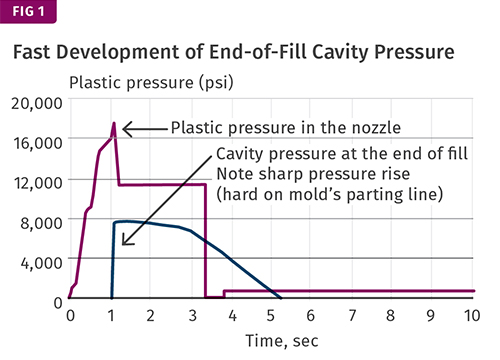
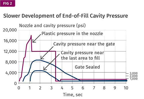
First, I am not a fan of smacking the parting line of my mold as shown in Fig. 1. I prefer a more gentle build of cavity pressure to minimize parting-line wear and flash, as shown in Fig. 2. Granted, this is not always possible due to numbers 4 and 6 on our list above. Still, my strategy is to fill the cavities uniformly to at least 90% full by volume and use second stage to pack the part to replicate the steel cavity texture, shape, and dimensions. I shoot for peak cavity pressure to occur during second stage, not first stage.
As both of these graphs show, for this part the peak injection pressure is about 17,000 psi. Hold pressure is much lower—nearly 8000 psi plastic pressure in Fig. 1, and 4000 psi in Fig. 2.
In both cases, you will get some bounce-back, since plastic is compressible and hold pressures are significantly lower than the peak injection pressures. The force of the plastic pressure will push the screw back if the machine allows it (most hydraulics will; most electrics will, but some do not). This does not mean the flow front hesitates, again due to the compressibility of the molten plastic.
You should also note the room-temperature density of your polymer vs the melt density. For polypropylene, the room-temperature density is about 0.90 g/cc, while melt density is about 0.71 g/cc. Because of these factors, some bounce-back is acceptable in most processes.
I am not saying it is OK for the flow front to stop or hesitate, as that is a disaster in most cases. I am saying that you can have some bounce-back, but because of the pressures involved and the compressibility of the plastic, the flow front will not hesitate. It might slow down a bit, but not hesitate. If your part can handle this slowdown, fine. But if you have a living hinge near the end of fill, you probably will want to minimize bounce-back.
Bottom line: Consider all the perspectives of forming the part you are working on—“think like plastic” (not easy to do)—and test your part to ensure it performs as required. Sorry folks, there just is not going to be an ISO or TS procedure that any person can follow to develop a functional process. There is a reason a good processor is a skill in demand.
Related Content

A Simpler Way to Calculate Shot Size vs. Barrel Capacity
Let’s take another look at this seemingly dull but oh-so-crucial topic.
Read More
Tunnel Gates for Mold Designers, Part 1
Of all the gate types, tunnel gates are the most misunderstood. Here’s what you need to know to choose the best design for your application.
Read More
How to Get Rid of Bubbles in Injection Molding
First find out if they are the result of trapped gas or a vacuum void. Then follow these steps to get rid of them.
Read MoreRead Next

INJECTION MOLDING: ‘Know Your Machine’
Many molders think they “know their machine,” but in reality do not. They get consumed by the demands of day-to-day production requirements and lose sight of the big picture.
Read More
INJECTION MOLDING: How Does Your Machine Control Pack Velocity?
You’ll need to find out in order to develop a molding process that you can repeat from machine to machine and mold to mold.
Read More
How Polymer Melts in Single-Screw Extruders
Understanding how polymer melts in a single-screw extruder could help you optimize your screw design to eliminate defect-causing solid polymer fragments.
Read More