
Injection Molding Simulation Meets the Real World
Direct data interface between molding simulation and the injection machine links the computer model to the real-world process. This can improve results from product and mold design through ongoing production. A case study demonstrates these benefits for automotive components in a family mold.


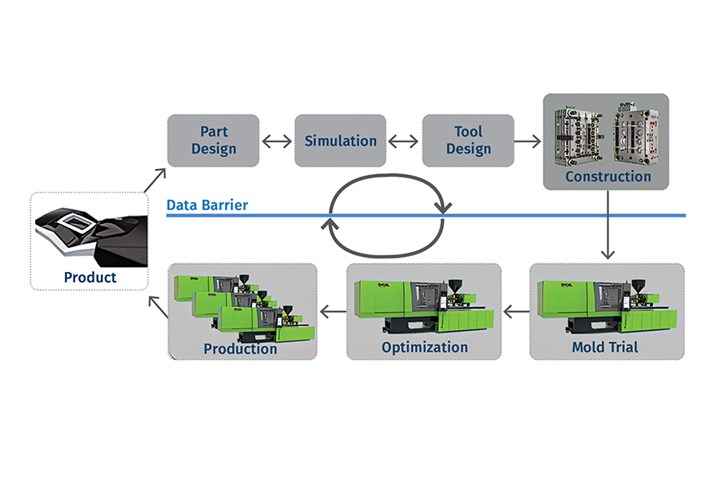
FIG 1 The sim link interface for data exchanges between the simulation program and Engel injection molding machine surmounts the data barrier and simplifies collaboration between simulation experts and process technicians. (Pictures: Engel)
With today’s digital tools, a wealth of information is generated even before mold configuration for a new injection molded product. Simulation is used, for example, to identify possible gate locations, check the filling behavior of cavities, set boundary conditions for the injection molding process, and optimize mold cooling. When the results of the simulation are satisfactory, mold production can begin, followed by pilot sampling, optimization of machine settings and, finally, series production. During sampling, however, cavities often need to be reworked to achieve the required product quality. This can drive up project costs significantly and lengthen time-to-market for the new product.
The fact that many process parameters defined in the simulation are not transferred to the production process is one possible cause of extra work. Why is this the case? The main problem lies in the time-consuming conversion of values generated by the simulation process in order to make them useful. Moreover, simulation technicians receive virtually zero feedback on the quality of the configuration data record supplied with the mold or the quality of simulation.


First, simulation and injection machine controllers need to learn how to talk to each other in the same language.
Aiming to break through this data barrier, Engel developed a data interface, called sim link (Fig. 1), that facilitates direct transfer of parameter settings defined through simulation prior to mold production to the control unit of the injection molding machine in the form of an initial set of proposed settings. Conversely, this interface also enables the transfer of real-world process data from the molding machine back to the simulation environment. The aim is to enhance the quality of simulation through an iterative progress. In this way, simulation technicians and production technicians can use each other’s knowledge and results and learn from one another.
More Realistic Simulation = Greater Benefit
The accuracy of simulation depends largely on modeling and the quality of material data; in other words, it is a “garbage-in/garbage-out” system. The more realistic the simulation, the better the results and the greater the benefits of simulation. The sim link interface therefore works equally well as a postprocessor to export initial settings for the injection molding machine and as a preprocessor for import of production data to the simulation environment. Thus, sim link aims to generate an initial set of proposed settings from simulation for an injection molded product while steadily enhancing the quality of simulation via feedback from production. To this end, sim link is equipped with three functions: Modification, Export and Import.
In the Modification function, the boundary conditions and process settings of the simulation are compared with the injection molding machine envisaged for the product. For example, target dynamics are included in the boundary conditions, and the process settings from the simulation are checked on the basis of machine limits. Modification makes it possible to gauge whether a product can actually be manufactured on the selected molding machine.
In Export, proposed initial settings for sampling the new mold on the machine are received and directly transferred to the control of the Engel injection machine. The boundary conditions for the simulation are thereby converted in such a way that they can be written into a part data set for the molding machine with settings values that can be properly interpreted by the controller. Process parameters and profiles are automatically compared with the limit values of the selected machine. In this way, the processor can make a more efficient start to production using settings that have been tested in simulation.
An injection machine database ensures that simulation is performed with accurate modeling of actual machine capabilities.
In the case of Import, the reverse applies: Real-world parameter values and signals from the production machine are channeled back to the simulation program. Using this feedback, the simulation technician can verify the quality of the simulation, compare pressure curves and build up expertise.
The current version of sim link works with two simulation tools—Moldflow from Autodesk and Cadmould from Simcon. The data interface is compatible with Engel injection molding machines with CC200 and CC300 control units; no additional software or hardware are needed.
The proposed settings generated by sim link can be transferred to the injection machine in various ways. Data transfers are possible via a company network (such as a net drive or MES) or via the internet. Transfers can also be carried out with a USB stick if the machine is not networked. Sensitive data such as CAD files and information on complete simulation projects remain in the local systems of the user and are not required for the utilization of sim link. Only the necessary parameters and settings are transferred via the interface, whereby the user has full transparency regarding data traffic at all times.
Back-and-forth sharing of preliminary settings determined via simulation and real-world molding process results helps refine both the simulation and optimal machine setup.
Putting It to the Test
 FIG 2 Trials with mineral-filled PP on a family mold for a car door interior trim, map pocket and a stiffening element demonstrate the user value of sim link. (Photo: iStock.com/Traimak_Ivan)
In partnership with Oerlikon HRSflow and Borealis, Engel subjected sim link to extensive practical testing. A family mold with three cavities and one hot-runner cascade with eight servoelectric nozzles was put into production. The parts in question were the interior trim for a car door, a map pocket and a stiffening element, all to be produced from polypropylene with 7% mineral filler (Fig. 2).
The settings for production of the parts would be determined and optimized through simulation. The focus of optimization was a constant flow-front velocity across all three cavities and optimum switching points for the servoelectric nozzles of the hot runner. In this family mold with cavities of varying sizes, the biggest challenge was to coordinate the cascading of the hot-runner nozzles to the flow-front position.
The simulation model was set up in Autodesk Moldflow and contained the cavities, the entire hot runner, the servoelectric needle shutoff nozzles and the machine nozzle, including some of the space in front of the screw (Fig. 3). Mold cooling was also included in the simulation.
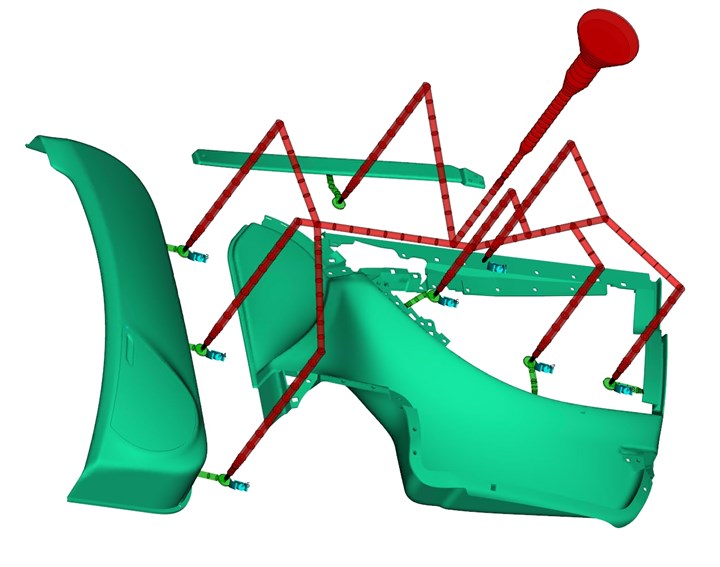
FIG 3 The Autodesk Moldflow simulation model for the automotive hot-runner family mold has eight servoelectric valve-gate nozzles.
First, a machine-independent simulation was performed using a relative injection profile, whereby the injection speed was defined as a percentage volume flow via the filling level of the cavity (Fig. 4). As a result, the melt-front velocity at any point in the cavity is independent of the melt compression in the system.
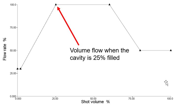
FIG 4 First, a machine-independent simulation was performed using a relative injection profile, whereby the injection speed was defined as a percentage volume flow via the filling level of the cavity.
The aim was to maintain a constant flow-front velocity throughout the filling process. The switching points for the individual hot-runner nozzles were defined on the basis of the flow-front position during filling. It was specified that the flow front in the cavity would meet the flow front from the nozzle at the respective gate. This is easily possible with the initial machine-independent simulation; the opening times for individual nozzles are fully decoupled from one another and from melt compression in the system. This showed that by choosing machine-independent simulation, even a complex system can be optimized very quickly and with few iterations in the simulation.
Process Optimization Through Simulation
In the machine-independent simulation, all initial settings were determined and modified for the chosen injection molding machine using sim link. To optimize the process further on the basis of the specific production machine, the machine-dependent settings obtained were simulated again.
Since the result with the machine-dependent and therefore very realistic parameters was highly satisfactory, an initial data set was generated for sampling and exported to the CC300 control unit of the production machine.
Needle-opening settings were manually entered in the HRS FLEXflow control unit on the basis of values obtained from the simulation. When starting up the injection machine, the real switchover point was subsequently set to match the simulation. No other optimization steps were needed to produce parts of the requisite quality.
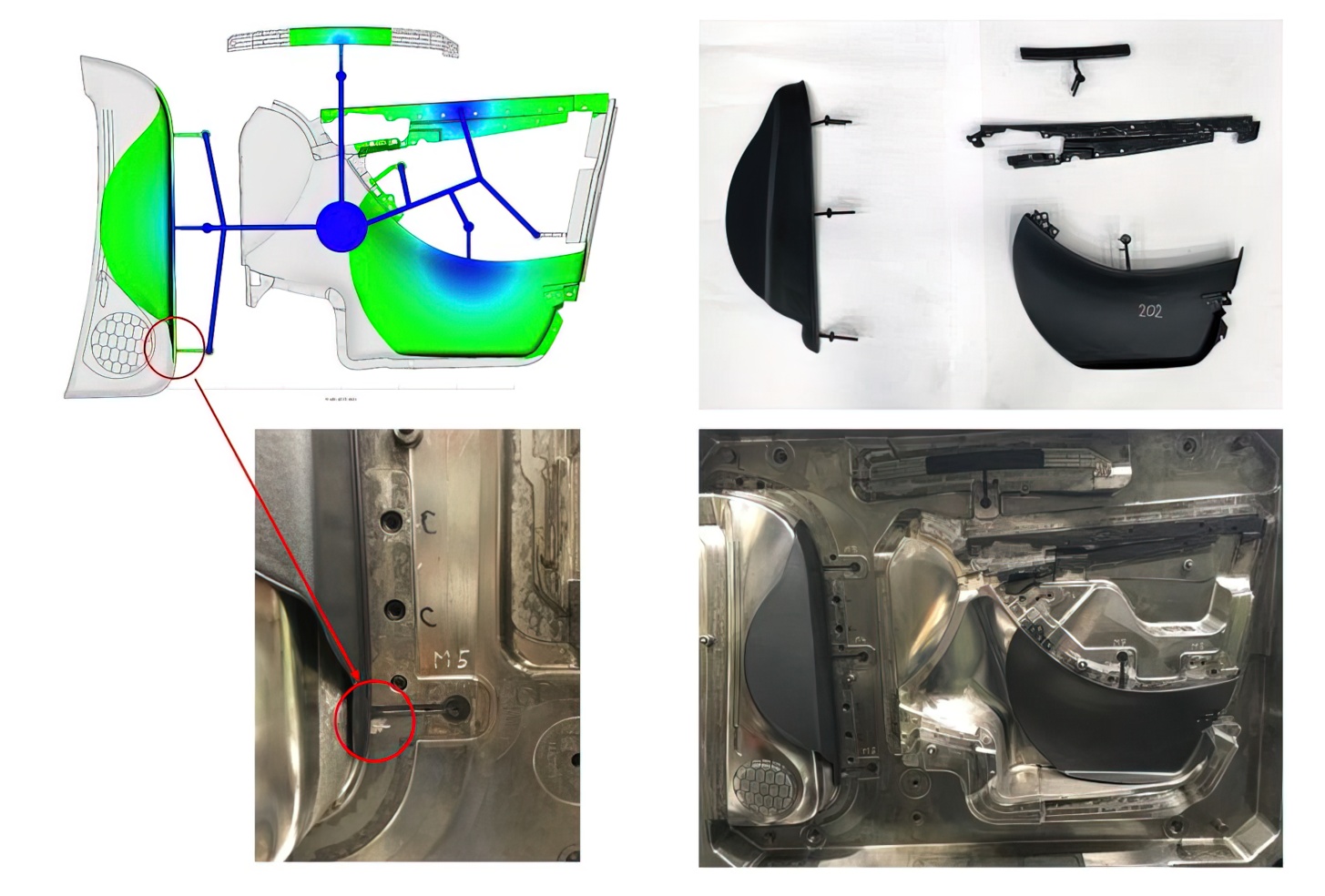
FIG 5 Snapshot of the filling process at the opening time of the needle shutoff nozzle marked with an arrow. There was a very high level of concordance between the simulation data and actual short shot.
Figure 5 shows a snapshot in the filling process at the opening time of the needle shutoff nozzle marked in the image. In the simulation, care was taken to ensure that for all needle shutoff nozzles, the flow fronts for the respective cavity and the shutoff nozzle to be opened meet at the gate in order to avoid weld lines. The depiction shows a very high level of concordance between the initial simulation data and actual short shot.
Figure 6 depicts a snapshot at the time of switching from the speed-controlled injection phase to the pressure-controlled holding-pressure phase. Once again, the level of concordance between the simulation and actual parts is very high.
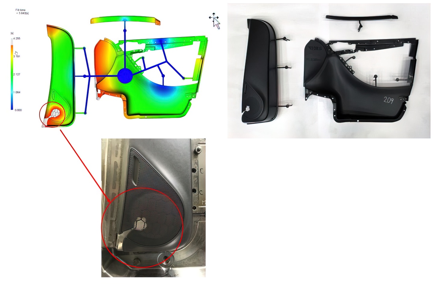
FIG 6 Snapshot at the point of switching from injection phase to the holding pressure phase also reveals excellent congruence between simulation and real-world parts (note area of detail highlighted).
Learning From Real-World Feedback
To provide the simulation technician with feedback on the usability of the setting parameters determined in the simulation, the part data and measurement results used in the real process were transferred back from the machine to the simulation program via sim link. Since sim link automatically edits and imports actual data from production, the simulation technician can start on the post-simulation immediately; there is no need for tiresome manual input of values and profiles. Of particular value is the fact that the actual machine behavior is transferred to the simulation program with the actual profiles, including oscillation of the injection pressure during switchover until the required holding pressure is reached.
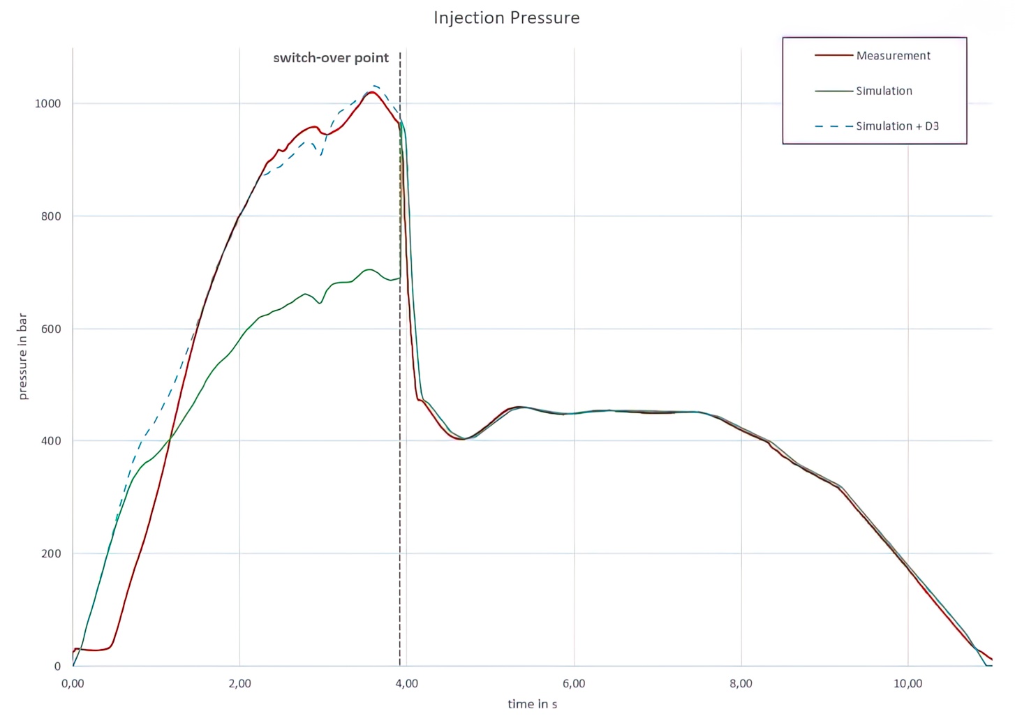
FIG 7 Comparing the injection-pressure curves shows that the simulation predicted a much lower peak value than was measured in the molding process, despite using realistic process settings. However, the pressure dependence of the viscosity was not measured on the initial molding trial. Adding the factor D3 for pressure dependence of viscosity produced a simulation result much closer to the actual molding trial.
The simulated flow-front velocity corresponded very well with the actual injection parameters. When comparing the injection-pressure curves in Fig. 7, it is apparent that the simulation predicted a much lower peak value than the curve measured in the molding process, despite using realistic process parameters. A close look at the material parameters (Moldflow “triple gold standard”) shows that the pressure dependence of the viscosity was not measured. In the cross-WLF model, which is generally used, pressure dependence is described with the parameter D3; in this case, D3 = 0. Better congruence between the measured and the simulated pressure curves was quickly achieved by empirically adjusting this parameter.
Feedback from production helps the simulation technician to develop a better feel for the materials used in production as well as the quality of the associated process parameters. In this way, the quality of simulation for other applications is enhanced. For example, more accurate pressure forecasts can be made for subsequent projects.
Comparison of the cavity-pressure curves can also provide additional information on such aspects as the quality of material parameters stored in the simulation database. Cavity-pressure development has a major influence on the shrinkage and warpage of the molded part in question. Accordingly, the aim is to predict cavity-pressure development as accurately as possible via simulation.
Modification of simulation parameters according to the selected injection molding machine makes it possible to use more complex injection profiles and realistically assess cycle times. Feedback from production helps to improve the quality of simulation and thereby avoid costly mold reworking.
ABOUT THE AUTHOR
Alfred Angerer is a development engineer in the field of smart production at Engel Austria in Schwertberg. He has been with Engel since 2018 in digital injection molding development with focus on the interface between process simulation and the injection molding machine and on building a digital twin of the injection machine. He studied mechatronics at the JKU in Linz, Austria, from 2003 to 2009. After obtaining his degree, Angerer worked at Profactor GmbH as a developer and project manager in robotics, thermography and machine vision. Contact: alfred.angerer@engel.at; engelglobal.com.
EDITOR’S NOTE
Several injection machine builders are exploring different approaches to integrating flow simulation with injection molding machine controls. In this article, the author presents one approach and the potential benefits it offers.


Related Content

How to Mount an Injection Mold
Five industry pros with more than 200 years of combined molding experience provide step-by-step best practices on mounting a mold in a horizontal injection molding machine.
Read More
What to Do About Weak Weld Lines
Weld or knit lines are perhaps the most common and difficult injection molding defect to eliminate.
Read More
How to Stop Flash
Flashing of a part can occur for several reasons—from variations in the process or material to tooling trouble.
Read More
How to Reduce Sinks in Injection Molding
Modifications to the common core pin can be a simple solution, but don’t expect all resins to behave the same. Gas assist is also worth a try.
Read MoreRead Next

Molding Simulation Added to Injection Machine Controls
Arburg and Wittmann Battenfeld are integrating filling simulation to aid in machine setup.
Read More
Simulation Is Making Injection Machines Smarter
Engel’s simlink will refine offline simulation with results from actual molding and use Engel’s machine data to constrain simulation within the actual machine’s capabilities.
Read More
Why Put Flow Simulation on an Injection Machine?
This emerging technology sounds promising, but its practical benefits have yet to be demonstrated clearly.
Read More