
Liquid CO2 Spot Cooling Gets Into Tight Spots in Molds
Close Up: Mold Cooling
Cooling of long, thin cores, fillets, slides, ejectors, or other hard-to-reach spots in injection molds can present difficult challenges.

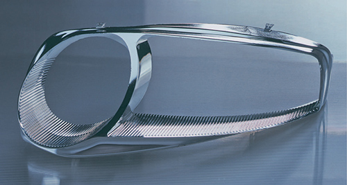
Adding liquid-CO2 spot cooling to the very thin center fillet, where water cooling could not reach, in this auto headlamp bezel, cut cycle time by 50%.
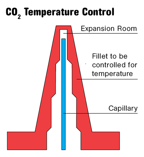
Feeding controlled pulses of liquid CO2 through a thin capillary tube gets powerful cooling into thin mold cores and other hard-to-reach spots. The CO2 expands in the “expansion room” and the gas escapes back around the outside of the tube.


Cooling of long, thin cores, fillets, slides, ejectors, or other hard-to-reach spots in injection molds can present difficult challenges. Sometimes water just can’t get there. And even if it can, water channels in such confined areas can be susceptible to clogging with scale deposits, and small cooling-channel diameters cause high pressure losses, which limit cooling capacity.
A proven solution to this problem, which has been used for several years in Europe, is now being introduced here by Linde North America, Inc., Murray Hill, N.J., a major supplier of industrial gases. Linde’s spot-cooling method uses liquid CO2 injected in controlled pulses through tiny capillary tubes inserted into the mold cores or wherever extra cooling is needed. The flexible stainless-steel capillaries (0.8 or 1.6 mm OD) are inserted into holes of 2-mm diam. or smaller drilled or EDM eroded into the mold, leaving a head space, called an “expansion room,” beyond the end of the capillary (see diagram).


Liquid CO2 is fed under high pressure (60 bar) to keep it from evaporating before it reaches the end of the tube. When it reaches the end of the tube and the expansion room, the CO2 expands into a “snow and gas” mixture at around -79 C (-110 F), which has high cooling capacity due to the sublimation energy of the transition from solid CO2 to gas. The CO2 extracts heat from the mold and escapes from the mold through the annular gap between the capillary tube and the mold channel.
This approach is meant to supplement conventional water cooling by ensuring uniform mold temperature without hot spots. The liquid CO2 is intended only to bring the temperature of hard-to-cool areas to the same level as the rest of the mold.
Spot cooling is retrofittable to existing molds. To feed the liquid CO2 in controlled pulses requires a controller to actuate solenoid valves at each capillary location on the mold. All the controller needs is a start signal from the molding machine—for example, when the mold closes.
In one application, a well known German maker of headlight housings had trouble cooling the very thin mold fillet in the center of the headlamp bezel (photo), where water cooling could not reach. This resulted in long cycle times. Adding CO2 spot cooling to this two-cavity mold cut the cycle time by 50%, a result said to be not unusual for this technique.
According to Andreas Praller, applications manager at Linde AG in Germany, at least 20 molders are actively using CO2 spot cooling in Europe, mostly for automotive applications. The technique reportedly attracted favorable attention at the NPE2012 show in Orlando, Fla., last April, mostly for uses in medical, household, and industrial products.
Related Content
-
How to Mount an Injection Mold
Five industry pros with more than 200 years of combined molding experience provide step-by-step best practices on mounting a mold in a horizontal injection molding machine.
-
How to Optimize Pack & Hold Times for Hot-Runner & Valve-Gated Molds
Applying a scientific method to what is typically a trial-and-error process. Part 2 of 2.
-
How to Stop Flash
Flashing of a part can occur for several reasons—from variations in the process or material to tooling trouble.


