
Look Before You Leap: When Direct Extrusion Makes Sense
The process offers great opportunities to extrude a better product at less cost, but it’s not for everyone. The formulation, product mix, and anticipated volumes must be carefully assessed to determine whether DE is the preferred manufacturing methodology.
Unlike in flood-fed single-screw extruders, the pressure gradient in a starve-fed twin-screw is zero for most of the process. This makes it easier to feed or vent along the barrel at various locations.
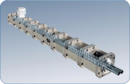
Co-rotating twin-screw extruders utilize segmented screws, assembled on high-torque splined shafts, and modular barrels with internal liquid-cooling bores.
TSE with a gear pump feeding a die in a flat-film/sheet process.
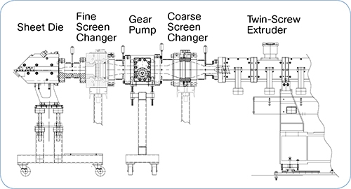
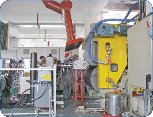
Typical line setup for a direct extrusion application. A gear pump is an essential element, since a twin-screw extruder is not a pressure-generating device. When using reclaim, filtration is often necessary before and after the pump.


In direct extrusion (DE), materials (pellets, fillers, fibers, and additives) are converted directly into the final product—usually flat film, sheet, fibers, or profiles—bypassing pelletization. Twin-screw extruders are generally required for such inline compounding and extrusion. The technology offers extrusion processors cost and time savings and improvements in product quality as well.
DE technology has been around for more than 40 years, but only over the last decade or so have processors more familiar with conventional single-screw extrusion embraced the idea. Discounting PVC applications for pipe, profiles, and the like—which technically qualify as compounding—about 50 DE lines are running now in North America, many of which have been installed over the last few years. Yet despite the advantages DE offers, it’s not easy for processors to make the transition. And the process is not suited for every application. DE is generally a better match for higher volume, dedicated production systems, as opposed to lower-rate lines that require frequent product and/or formulation changeovers.


Processors should do some analysis before jumping into DE. For one thing, they need to realize that twin-screw extruders work much differently from singles. Moreover, upstream complexities associated with raw-material handling and feeding must be integrated with nuanced die and downstream systems required for tight-tolerance products. Often, a dozen or more suppliers are needed for an installation. Because of the system complexity, the upfront investment for a DE line is typically higher than for a conventional single-screw system. Almost without exception, direct extrusion applications require developmental efforts to define the scope of the production system.
GETTING TO KNOW TWINS
You first need to understand what twin-screw extrusion is all about before you even consider moving into DE. High-speed, energy-input (HSEI) twin-screw extruders (TSEs) are typically utilized for compounding, devolatilization, and reactive extrusion, which are mass-transfer dependent processes. Historically, TSEs have produced pellets, which are subsequently fed into an extruder, injection press, or blow molder. But when you are processing a sheet, film, profile, or fiber from a TSE, the dimensions are generally far more critical then when you are making a pellet.
Initial DE applications were mandated—often in desperation—for formulations that were adversely affected by the second heat and shear history inherent with separate steps for compounding/pelletizing and single-screw extrusion of a finished product. Early examples included processing of undried PET, conductive electronic compounds, and fiber-reinforced products. These efforts spawned an understanding of DE that has been applied to commodity products to save the conversion costs associated with toll compounding.
Co-rotating (and counter-rotating) HSEI TSEs utilize segmented screws, assembled on high-torque splined shafts, and modular barrels with internal liquid-cooling bores. The motor inputs energy into the process via rotating screws that impart shear to the materials being processed. Segmented screws and barrels, in combination with the controlled pumping and wiping characteristics of the co-rotating, self-wiping screws, allow screw/barrel geometries to be matched to the process tasks. Solids conveying and melting occur in the first part of the process section. Screw elements for mixing and devolatilization are then integrated into the design. Discharge elements then build and stabilize discharge pressure.
The free volume in a TSE process section is related to the OD/ID ratio, which is defined by dividing the outside diameter (OD) by the inside diameter (ID) of each screw. The torque-limiting factor for a HSEI TSE is the screw shaft, based upon its cross-sectional area; the geometry of the shaft; the material of construction; and fabrication techniques. Deeper screw flights result in more free volume, but with less torque, since a smaller-diameter screw shaft is mandated. Regardless of the final product (pellet or part), it is vital to know the heating/cooling design, available free volume, and torque rating for any HSEI TSE and the boundary conditions of the intended process.
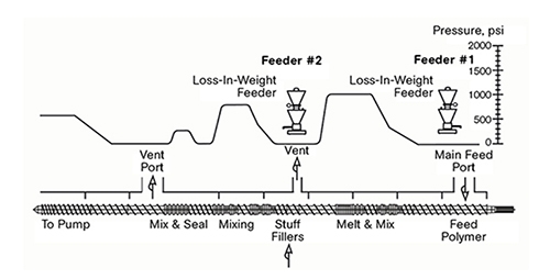
HSEI TSE are starve fed (whereas singles are flood fed), with the output rate determined by the feeders, which meter pellets, liquids, powders, and fibers into the process section. Feeders maintain formulation consistency and introduce ingredients in the proper order. The TSE screw rpm is independent of the feed rate and is used to optimize compounding efficiencies. Because the pressure gradient is controlled (and in fact is zero for much of the process), materials are easily introduced into downstream barrel sections to facilitate sequential feeding to minimize wear and avoid the high shear associated with plastication.
Often a side stuffer is integrated with the TSE to push fillers, fibers, etc. into the melt stream of the TSE process section after melting. The rate of downstream addition is set by the loss-in-weight feeder, not the side stuffer. The extruder screws at the side stuffer move the materials forward while providing a relief vent for entrapped air and moisture that is flashed.
DE systems are significantly more complex than single-screw extrusion systems, since a starve-fed HSEI TSE must also consistently pump to a die, with melt temperature playing a more important role. The die and downstream system will be the same as if a single-screw extruder was processing a pre-compounded pellet.
Here is an overview of various components of a DE system:
•Metering feeders: The feeding system for a DE system is particularly critical, as the average mixing effect inherent in the secondary single-screw extrusion step is lost. Feeders also play a major role in pressure stability. Therefore, gravimetric feeders, rather than volumetric types, are required for most DE applications. Material-handling and refill equipment also plays an important role.
•Twin screw extruder: The heart of any DE system is the TSE, which performs the same mass-transfer operations as if it were mated to a pelletizer. The TSE process section is often lengthened so that the latter sections of the screws are dedicated to pumping, and a gear pump (described below) is often utilized. In general, it is better to upsize the TSE and operate it at a lower screw rpm as compared to using it in a pelletizing system. In the context of the overall system cost, the additional investment to upsize is negligible, and often well worth it.
•Gear (or screw) pump front-end attachment: A gear pump is a positive-displacement device that builds and stabilizes pressure, allowing the TSE to perform mixing and devolatilization with less emphasis on pumping. It also facilitates a lower front-end pressure that results in less over-flight mixing at the TSE discharge and thus a lower melt temperature. Alternatively, a short single-screw pump front end (10:1 L/D) may be used. This is essentially the metering section of a single-screw extruder that avoids plastication and compression, primary causes for pressure instability in a pellet-fed single-screw extruder.
•Screen changers: There are many different types of discontinuous and continuous screen changers. If coarser filtration levels are specified, and/or if there are high levels of contaminants in the melt stream, then the screen changer should be situated before the gear pump. Reclaim materials sometimes require filtration both before and after the gear pump. Filtration can be a tricky part of a direct extrusion system and needs to be thoroughly investigated and carefully managed.
•System controls: Typically, a PLC-based control system is required to manage the system, as well as to facilitate recipe retrieval and data archiving. The 15-sec. to 2-min. residence time for the materials in a TSE must be taken into account by the pressure-control algorithm.
A possible control scenario is for the gear-pump rpm to be locked to set a constant volumetric delivery rate to the die. The tuning algorithm analyzes the inputs from key points in the system, makes numerical calculations, and applies corrections to the TSE screw rpm and feed rate. The objective of the algorithm is to maintain the gear-pump inlet pressure at a setpoint.
When sequential feed streams are being introduced into the twin screw extruder at various points, closed-loop pressure control becomes more complicated, as various residence times must be managed. With a stable melt delivery to the gear pump, the discharge flow and pressure to the die will be uniform, which is the ultimate objective of the entire system.
REAL-WORLD APPLICATIONS
Providing a usable melt to the die and downstream system is only half the battle. Next, the correct die and downstream equipment are required, whatever the final product. The following provides some examples of where direct extrusion has been successfully deployed:
•Battery separator sheet: A PE/silica/oil formulation is fed into the extruder feed throat and oil is injected into a barrel section in the early stages of the process. The materials are mixed and devolatilized in the TSE process section, which is directly coupled to a sheet die. After the die, a high-pressure calender “squeezes” the extrudate and sets the final dimension, eliminating the necessity for a gear pump and closed-loop pressure control.
•Foamed profiles: The polymer(s) is fed into the TSE and melted prior to injection of a supercritical fluid (i.e., CO2), which is intimately mixed at elevated pressures with high-division distributive mixers to minimize viscous heating. The latter part of the TSE process section uses low-energy-input pumping elements so that the barrel sections serve as a heat exchanger to cool the melt. A single-screw pump is mated to the front end of the TSE for pumping/pressure generation and additional cooling. The TSE/single-screw extruder configuration has proven more versatile than tandem foam systems with two single-screw extruders.
•Filled film/sheeting: The polymer(s) and additives are fed into the main feed throat and melted prior to the downstream introduction of fillers into the melt stream via a side stuffer. The materials are mixed and devolatilized in the TSE, which is typically mated to a screen changer and gear-pump front-end assembly. Examples of filled products include TPO roofing membranes, conductive carbon-black sheeting, and diaper films.
•Adhesive compounding: Rubbers, tackifier resins, fillers, and oils are mixed and devolatilized in the TSE with a gear pump mated to a rod (or film) die for direct glue-stick profile (or laminate) extrusion. In some instances, the TSE has proven superior to separate twin-screw compounding and single-screw extrusion operations, as a de-mixing effect often occurs as the materials coalesce in the single-screw process.
•Wood-fiber composite products: The primary functions of the TSE in this application are to remove water and distributively mix the natural fibers into a polymer carrier. Fibers are introduced into the melt stream by a side stuffer, and multi-stage venting occurs. A gear pump is mated to the front end of the TSE to ensure low front-end pressure to avoid degradation of the fibers. Examples include profiles for decking and sheeting.
•Undried PET/PLA film and sheet: Undried PET or PLA is metered into the TSE process section with multi-stage vent ports and vacuum venting to minimize hydrolysis. Reclaim materials may require multi-stage screen changers situated before and after the gear pump for coarse filtration prior to fine filtration. Use of the TSE in this application results in significant energy savings, as predrying of the PET or PLA can be eliminated.
There are many successful DE installations worldwide, most of which are highly proprietary. DE offers great opportunities to extrude a better product at less cost, but it’s not for everyone. The formulation, product mix, and anticipated volumes must be carefully assessed to determine whether DE is the preferred manufacturing methodology. When appropriate, the benefits are well worth the time and effort to implement this advanced, well-proven technology.


Related Content

Davis-Standard to be Systems Integrator for Novel EDI Flat Die
Die uses motorized lip-adjustment, said to be three to five times faster than heated-bolt adjustments.
Read More
Die-Service Cart Upgraded to Handle Screws, Chill Rolls
Processing Technologies International LLC has released its next-generation flat die servicing system, the uCAMS (Universal Cleaning Assembly and Maintenance System) Plus.
Read More
PTi Makes Changes in Leadership Structure
Moves aimed at bolstering the future of the sheet extrusion manufacturer.
Read More
Macro Names Anzini Tech Sales Manages for Southeast
Has worked in technical roles for leading processing companies in his career of 40+ years.
Read MoreRead Next

Why (and What) You Need to Dry
Other than polyolefins, almost every other polymer exhibits some level of polarity and therefore can absorb a certain amount of moisture from the atmosphere. Here’s a look at some of these materials, and what needs to be done to dry them.
Read More
Troubleshooting Screw and Barrel Wear in Extrusion
Extruder screws and barrels will wear over time. If you are seeing a reduction in specific rate and higher discharge temperatures, wear is the likely culprit.
Read More
Understanding Melting in Single-Screw Extruders
You can better visualize the melting process by “flipping” the observation point so that the barrel appears to be turning clockwise around a stationary screw.
Read More