
Look Upstream to Avoid ‘GIGO’ Pitfalls in Extrusion
You may think you have a feeding issue when in reality your problem may be upstream.
Everything upstream of the extruder can be viewed as a single “pre-conversion” system, each element of which can contribute to or compromise formulation quality.
On-line proportioning of blend components can be flexible, reliable, and precise, but is not without its own potential pitfalls.
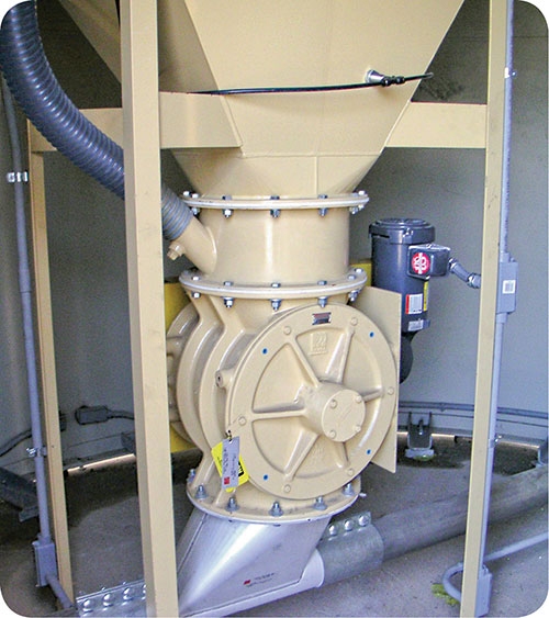
n the pickup stage, material is introduced to the conveying line by the method most conducive to reliable supply. Here a rotary airlock feeds a floodable powder filler for transport.


In extrusion, you need to ensure that formulations arrive at the extruder accurately proportioned and properly conditioned. The familiar phrase “garbage in, garbage out” (or GIGO) should remind processors that no matter how well an extruder performs, any mis-formulation or interruption of the input stream will corrupt the result. If such problems do arise, the tendency is to blame the proportioning system due to its position immediately upstream of the extruder.
While no proportioning system is immune to problems or failures, it’s not unusual to find that the underlying cause of a formulation problem originated farther upstream. The proportioning system is the last link in a chain of operations that precede extrusion, any of which may contribute to or directly cause a difficulty. So everything upstream of the extruder—from initial receiving, storage, conditioning, and conveying of blend components through the proportioning operation itself—must be geared to produce and supply the extruder with a reliably consistent, on-spec formulation.


To avoid GIGO pitfalls, processors must view everything upstream of the extruder as part of a single “pre-conversion” system—a group of operational subsystems beginning with raw-material receiving and ending with the proportioning system’s discharge to the extruder. This pre-conversion system encompasses all of the purpose-based subsystems that may be required by the application: unloading and storage, screening, size reduction, classifying, conditioning, preblending, etc. Since the output of one subsystem is the input to the next, all these routine operations are, to some degree interdependent and must work in concert.
For the processor building a new extrusion line, a major benefit of taking such an inclusive view is to underscore the need for the tightest possible integration of pre-conversion system elements. And for those operating an existing line, this perspective will help speed diagnosis of problems as they are encountered and better inform any required remedial actions.
IDENTIFY GIGO PITFALLS UPSTREAM
To avoid a pitfall it must first be identified. With our fresh pre-conversion perspective in place, many GIGO pitfalls readily suggest themselves. Given the diversity of extrusion applications and process setups, it’s impossible to attempt a comprehensive assessment here. But it is possible to highlight many of the more commonly encountered pitfalls.
Begin at the end—the proportioning system—and proceed backwards against the flow of the process, ending where the process starts. In our journey upstream we assume that all materials, as initially received, are in acceptable, in-spec condition, and then we look to identify whatever states, conditions, actions, or influences may compromise the consistent production of a correctly formulated blend stream at the rate desired.
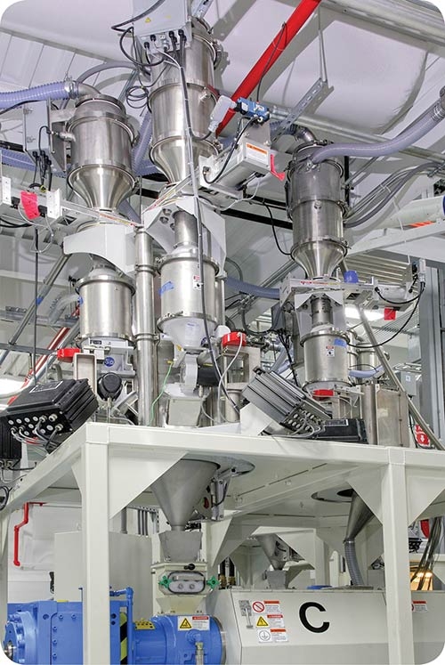
Most commonly, a continuous, on-line proportioning system consists of a number (usually six or more) of gravimetric (usually loss-in-weight type) feeders centrally located above the extruder. Each feeder (assumed to be appropriately configured) proportions its ingredient according to the recipe. Depending on the application, total recipe throughput may be held constant or permitted to vary, slaved to an extruder or other process parameter.
From the instant a component exits its feeder to the moment it passes through the extruder die, several factors can conspire to compromise the integrity of the result. First, today’s high-speed extruders with their lower residence times may leave little opportunity for complete dispersion and mixing of recipe components, placing an increased burden on the proportioning system to achieve its required performance accuracy within the shortened time scale. To deal with this, you should conduct pre-purchase testing of feeder performance based on the application’s anticipated extruder residence time, not the relatively lengthy sampling interval typical of conventional performance testing. Only in the light of realistic testing can competing systems be fairly assessed and potential improvements identified and evaluated.
Second, to avoid component segregation within the blend stream, the proportioning system is positioned directly above the extruder feed throat. However, in flood-fed extrusion, where a short column of the component mix is maintained above the throat, minor segregation may occur. Thus, if one or more components are found to be particularly prone to segregation in the column, the fix may be as simple as an appropriately positioned baffle or deflector inside the supply channel.
And third, in instances where a particular recipe component is fed by a single screw at an unusually low rate within its operating range, the combination of low metering-screw speed and the single screw’s innate geometry can result in discharge pulsing, corrupting the instantaneous blend. If not anticipated or accommodated at the application development stage, fixing this requires speed re-ranging along with a smaller and/or lower-pitch screw. Fortunately, software-based protection against this problem is available in the form of a screw-speed modulation technique that automatically varies rotational speed based on screw-flight position, resulting in an effectively pulseless discharge even at very low delivery rates.
FEEDER REFILL
Loss-in-weight feeding is typically employed to proportion blend components. Since this approach requires weighing the entire feeder and hopper along with its material content, the feeder’s integral hopper must be periodically resupplied. Automating refill typically requires the use of a gate, hopper receiver/loader, rotary valve, screw feeder, or other device suitably selected, sized, and configured to quickly recharge the feeder hopper.
In part because these common devices are also employed in operations other than loss-in-weight feeder refill, the importance of proper and adequate integration with a precision gravimetric feeder may be under-appreciated. The fact is that a poorly integrated refill device jeopardizes proportioning performance during refill and risks interruption of material supply altogether.
Although the refill operation may appear simple and straightforward, its effect on proportioning performance and consistency warrants close attention. During the refill phase, where material simultaneously enters and exits the feeder, sensed weight cannot be used to determine or control discharge rate. Less sophisticated feeding systems simply “freeze” metering speed at a constant value when entering refill and “unfreeze” it after refill, effectively turning the gravimetric feeder into a volumetric one for a time, and invoking a disruptive steplike metering-speed correction when refill is complete and gravimetric control resumes.
To preserve gravimetric-level performance during the necessary refill operation, a more refined approach involves memorizing the relationship between metering speed and actual sensed weight during the most recent gravimetric feeding phase and then applying that relationship to appropriately adjust metering speed as the hopper refills. This way, gravimetric-level performance is preserved and any abrupt control corrections are avoided.
The often overlooked pitfall of inadequate refill integration is best avoided right from the start. Aside from the more obvious considerations of proper sizing, discharge-rate sufficiency and the like, refill device integration should also attend to concerns of performance monitoring, control actions, and alarm logic.
AMBIENT INFLUENCES
Loss-in-weight proportioning can be especially sensitive to ambient influences because it must precisely and continually measure very small differences in the weight of a relatively massive load, the feeding system itself. And it must do so while installed atop an operating extruder.
Here, the term “ambient” is used in its broadest sense to refer to environmental factors and also to potential concerns stemming from improper installation and/or lax maintenance. Ambient influences on the crucial weighing operation include vibration transmitted to the proportioning system from nearby machinery, insufficiently flexible inlet/outlet connections, random shocks and mechanical disturbances, pressure variations within the system and at the process connections, and any broad swings in temperature. Even air drafts and currents in the processing zone, if excessive, could affect weighing performance.
As with any GIGO pitfall, however, the cause of the problem must first be identified before it can be fixed. And in the case of ambient influences, it is again best to avoid them at the outset, first through an informed appreciation of their potential corrupting effect on proportioning performance, and then by observing proper and conservative installation and maintenance practices.
For example, regular cleaning or replacement of hopper vent filters will minimize transient pressure buildup in the feeder’s supply hopper during refill. Resilient mounting pads or isolators will suppress the transmission of shock/vibration to the feeder. Installing flexible connections in their unstressed state will prevent rogue forces from affecting weight measurement. Proper routing of cables and wiring leading to and from the feeder will also help prevent contamination of weight measurements.
Even if the processor has been meticulous in pre-purchase testing and evaluation of alternative proportioning systems, the material presented to the proportioning system on the process line almost always differs from the material tested much earlier in the labs.
The questions are: How much different, and does the difference make a difference? It is nearly impossible for pre-purchase testing to reproduce precisely the conditions the process line impresses on the materials that flow through it. Fortunately, in the vast majority of cases the sample material supplied for developmental testing reasonably approximates the material encountered in the real world, and the feeder selected and configured for the test material can compensate for inevitable variations.
Of course, pitfalls are by nature unexpected. If online proportioning performance is not what initial testing suggests it should be, the process engineer might want to take a hard look at any changes in the material’s condition that may have occurred between initial receiving and the proportioning feeder’s inlet.
PREMIX PITFALLS
Off-line batch premixing of additives, colorants, etc. provides a flexible and convenient way to aggregate low-proportion components destined to join the primary blend stream on-line just prior to extrusion. Premix components are typically portioned out by hand on a high-precision scale. The premix is then thoroughly mixed before being transferred to its on-line masterbatch feeder.
While the manual nature of premixing allows high-accuracy proportioning of critical minor components, concerns of reliability and repeatability linger due to the chance of human error.
Unlike major recipe components, which remain separated until proportioned, masterbatch components arrive at pre-extrusion proportioning ideally in the form of a well mixed blend of often very dissimilar materials. Here the concern of segregation can arise. Even assuming the mixing operation to be fully effective, subsequently emptying the mixer, transporting the masterbatch to on-line proportioning, and dumping it into its feeder hopper risks at least some degree of segregation.
CONVEYING—NOT SO SIMPLE
The job of pneumatic conveying is often oversimplified as merely “sucking on straws” or “blowing darts,” depending on whether the material is to be pulled or pushed. But while pneumatic conveying sounds simple in concept, there is nothing simple about it. Using the force of air to move material efficiently, reliably, in the required amount, at the right time, and at the needed rate without undue damage, degradation, or change in material condition is among the most challenging system design tasks faced in processing.
The challenge is compounded by the fact that virtually every conveying installation is unique in both its application requirements and optimal design solution. Application variables of material, rate, plant layout, transport distance, elevation change, and much more contribute to the system’s inevitable uniqueness.
Add in the uncertainties of supplier capability, and where does that leave the extrusion processor in need of a solution? The unavoidable reality of GIGO along with our “pre-conversion” system perspective underscores the importance of conveying-system design becoming even more tightly integrated with its ultimate destination, the proportioning system.
Because it is so challenging, and because it is the most common form of automated conveying in extrusion, pneumatic conveying in general—and vacuum conveying specifically—earns primary focus here. By simply cutting it up into the following four core actions, a number of potential pitfalls and their consequences may then be identified and prevented or remedied:
1. Discharge: Working backwards in an upstream direction we encounter the receiver, the lower portion of which performs the final act of the conveying operation—discharge to the proportioning feeder when hopper refill is needed. Marking the transition from conveying to proportioning, this last act of conveying is as much a part of the proportioning system as it is of the conveying system.
The discharge device must suit the material. It’s typically a shutoff gate, butterfly gate, or flapper type for pellets; and a slide gate, screw feeder, or rotary valve for powders or regrind. Upon feeder refill request, the discharge process must occur smoothly and quickly to minimize refill duration. The device must also immediately and completely cease discharge when commanded.
Where a variety of materials are involved, proper selection and sizing of the discharge device for each material is paramount. While some materials, like most pellets, present little challenge in discharge, others may prove more difficult. Some powders, for example, may require the assistance of vibration or air pads to produce reliable discharge. And less than complete shutoff after feeder refill is likely to produce leakage into the feeder’s hopper, hindering proper proportioning. These and other vulnerabilities can compromise the discharge operation if not anticipated and addressed in initial system design.
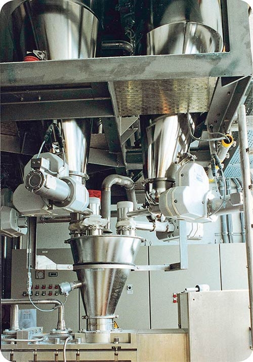
2. Receiving: One step farther upstream, we shift focus to the upper portion of the receiver where the material arrives from the transport line. Here, the incoming material must be separated from the conveying air, collected/accumulated, and retained until discharge. The typical cyclone-type receiver initiates operation by opening its vacuum and material inlet valves, drawing material from the transport system’s supply line for a preset duration to receive the required refill volume (usually about 70-80% of the feeder’s gross hopper capacity). An integral level sensor confirms adequate charging of the receiver. Because material enters the receiver tangentially, separation of the airborne material stream naturally occurs within the receiver, and the material drops out of suspension, accumulating above the discharge device. Simultaneously, conveying air is filtered (if appropriate) and exhausted. Here, properly sized filter surface area and surface treatment for the conveyed material and rate are important parts of the design stage. In addition, filter cleaning technique and timing are critical considerations in interfacing with the downstream feeding/blending system’s refill cycle.
These actions require close orchestration. An improperly sized receiver may not be able to adequately refill the feeder’s hopper. A clogged filter may impede or prevent required separation. Unanticipated process and/or environmental conditions may produce unexpected material flow difficulties within the receiver. Less-than-optimal coordination of these discharge sub-operations and interfacing to the downstream feeder can jeopardize the entire proportioning effort.
3. Transport: The most visible element in the transport portion of a pneumatic conveying system is the network of piping that routes material from pickup to discharge. Motive force is provided by either a vacuum pump or pressure blower. As needed, various other devices often punctuate the run, including diverters, proportioning valves, surge bins, filters, dryers, and the like. This carefully composed collection of components must meet the same mission-based metrics shared by all pre-conversion operations: correctness, consistency, and condition.
As applied to the transport subsystem, “correctness” requires that material be moved from point to point at the required rate. Pitfalls related to this metric most often stem from errors in core design issues involving component selection and sizing as well as inadequate consideration of the material, line routing requirements, and environmental factors such as ambient temperature, humidity and plant altitude.
“Consistency” refers to the ability of the transport system to function reliably and repeatably over time. Problems typically arise either from changes originating within the system (such as worn or scoured lines and rate variation or insufficiency due to unsteady pump or blower performance or a clogged filter) or changes from external influences (such as inflow problems at pickup, varying fines content in the material, and changing environmental conditions).
“Condition” underscores the importance of conveying without objectionable material alteration or degradation. Pneumatic conveying can be violent, so the material itself becomes the natural starting point for consideration. Conveying velocity must be sufficient for transport, but not so high as to mechanically or thermally degrade the material, possibly even compromising its role in the blend and/or its ability to be proportioned properly once discharged. Striking a workable balance can be a challenge. Additionally, some materials can result in accelerated wear on the transport’s piping as well as restrictive buildup.
Pneumatic conveying is, and will likely remain, part art and part science. Design and selection of the transport portion of a pneumatic conveying system is a true multi-disciplinary task—one that requires a firm grasp of the principles underlying the flow of both fluid (air) and solid materials, a mastery of the dynamics of their interactions, and a seasoned knowledge of how to translate that expertise to processing.
4. Pickup: Available modes of containment/storage range from silo-sized systems for high-capacity bulk storage to smaller supply bins, daybins, gaylords, IBCs, and drum or bag dump stations. Whether destined for vacuum or (positive) pressure conveying, the key concern in pickup is that the material be supplied consistently to the transport stream.
Pickup solutions range from large “pickup boxes” positioned beneath high-volume supply silos or hoppers to adjustable pickup wands for drawing up material from gaylords or daybins. Pellets and other free-flowing materials typically need little incentive to flow into the pickup device, but less cooperative materials often must be coaxed or forced. In such cases, an airlock, rotary valve, screw feeder, eductor, or other specialized solution may be required. Other forms of flow encouragement may also be employed, such as vibrators and air pads.
Considering the processing penalty paid for inconsistent pickup, the sometimes subtle challenge in providing a reliable solution—one that performs under all operating circumstances and conditions—must not be overlooked.
RECEIVING, STORAGE & PRECONDITIONING
We are finally approaching the beginning of our pre-conversion system. From the moment materials are delivered, received, transported, stored, handled, dumped, worked, or classified, they acquire a new history. Their characteristics and conditions may become altered as a result. Material that may have been on-spec as delivered may no longer be so by the time it is conveyed and arrives at the proportioning system. The consequences of such insidious changes in state, condition, or handling properties may affect processability downstream.
It is not possible here to individually address or resolve the many potential causes of material change in these early suboperations. But remember that such changes can and do occur in these initial process phases, and that if proportioning problems do arise, the condition of materials entering the proportioning system warrants close inspection. If found to be out of spec, investigation should be focused farther upstream in an effort to identify the cause of the change.
To zero in on process-related GIGO pitfalls, we assumed that all materials, as initially received, are in in-spec condition. Now that we have identified and discussed many of these pitfalls, be aware that this assumption may not always hold true.
Experience proves that materials’ processability can be sensitive to minor alterations in their composition or condition. This should serve as a reminder to processors to be on the lookout for unanticipated or unintended changes in the material, especially when considering new sources of material supply. Even apparently equivalent materials from separate suppliers can differ in some crucial way when passing through the process line. A processor’s own standards of material acceptability should be applied rigorously to routinely monitor and confirm the compliance of incoming materials.


Related Content

Captive Molder Beefs Up Auxiliaries to Boost Quality, Consistency
SeeScan adds conveying, drying, feeding and chilling technologies to improve quality — and enhance employee safety — in production of its underground/underwater inspection systems.
Read More
Weigh Scale Blenders Billed as Ideal for Mid-Range Throughputs
Blenders address growing demand to use PCR along with regrind, fillers and virgin polymer.
Read More
Versatile Weight-Loss Feeder
Compact, robust unit is permanently calibrated and adjustment-free.
Read More
Flexible Feeder Line Suited for All Processes
New feeder models are said to offer the ultimate in flexibility for injection molding, extrusion, blow molding and extrusion control applications.
Read MoreRead Next

How to Set Up & Maintain An Efficient Resin Handling System
In today's world, having a reliable resin-handling and conveying system is as important as having reliable electrical power.
Read More
Understanding Melting in Single-Screw Extruders
You can better visualize the melting process by “flipping” the observation point so that the barrel appears to be turning clockwise around a stationary screw.
Read More
Advanced Recycling: Beyond Pyrolysis
Consumer-product brand owners increasingly see advanced chemical recycling as a necessary complement to mechanical recycling if they are to meet ambitious goals for a circular economy in the next decade. Dozens of technology providers are developing new technologies to overcome the limitations of existing pyrolysis methods and to commercialize various alternative approaches to chemical recycling of plastics.
Read More