
Metal/Plastic Hybrid Molding: Flexible Alternatives for Teletronics
In overmolding of plastic onto electronic components, the goal today is flexibility. Here are three real-world examples of different kinds of modular cell layouts that have been used in production.

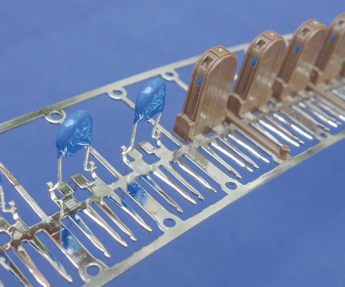
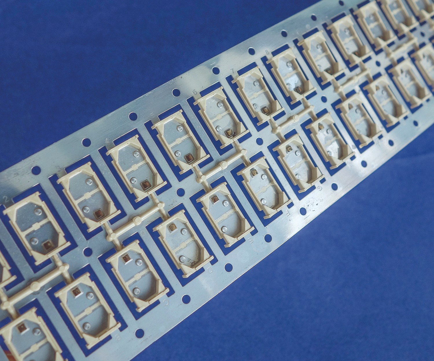
Linear cell systems produce hybrid teletronic components consisting of plastic overmolded onto a metal carrier strip.
Until recently, highly integrated hybrid molding cells have been dedicated to a single product. Now, flexibility is the goal.
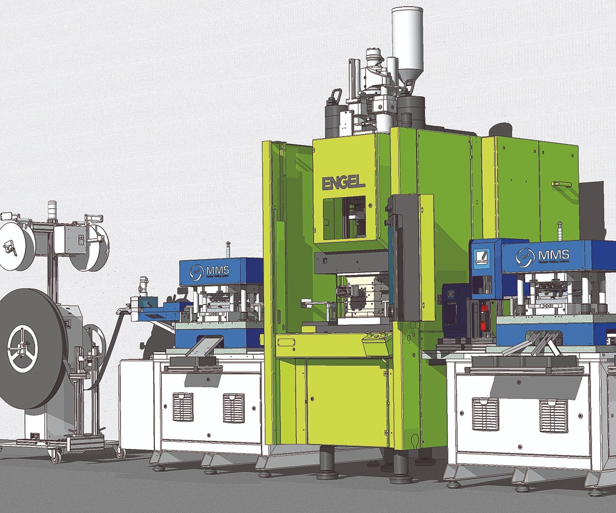
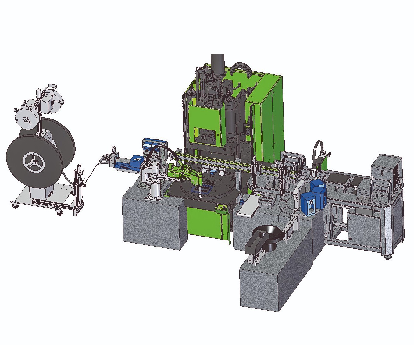
Case 1: This linear hybrid overmolding cell will be running live at NPE2018.
Case 1: Thermal switch housings of glass-filled nylon overmolded on a brass strip will be produced at NPE2018.
Case 2: Radial production cell for four-pin plugs with an LSR seal produces eight parts in 24 sec.
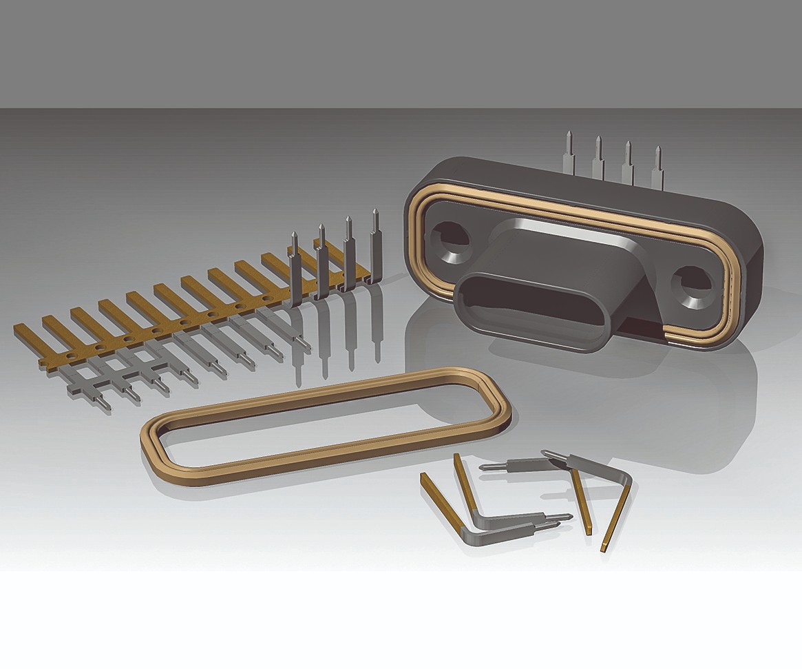
Case 2: Eight four-pin plugs of glass-filled PBT are overmolded onto metal and assembled with an LSR seal.
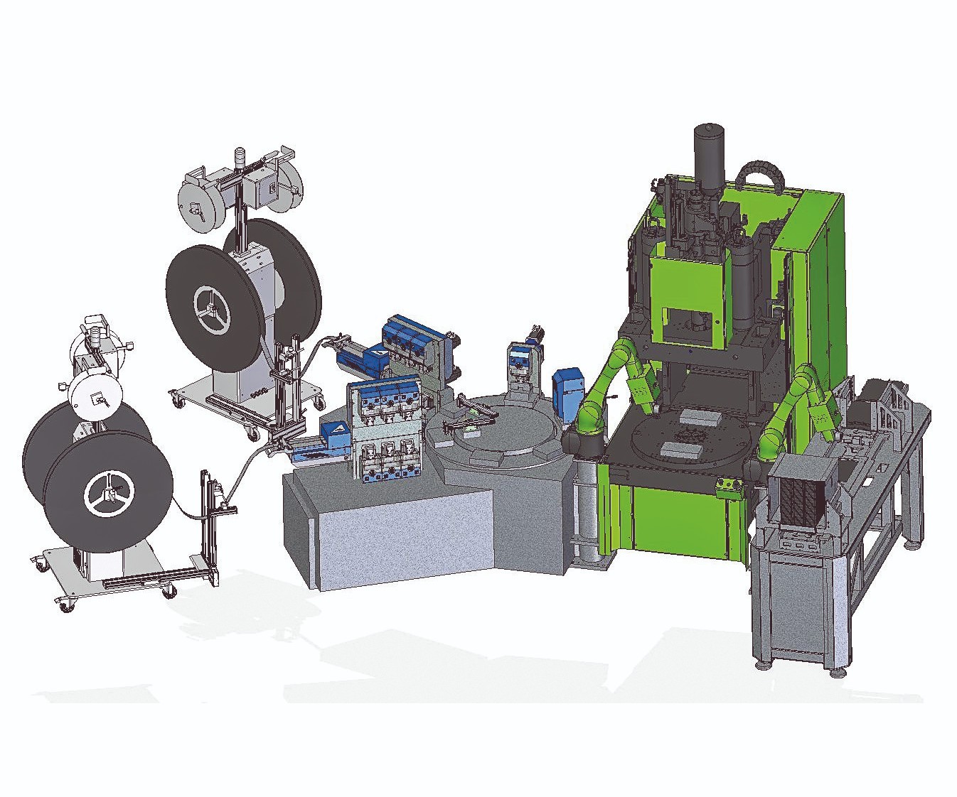
Case 3: Radial cell infeeds two strips to form the leadframe of contact elements. Two six-axis robots flank the vertical injection press.
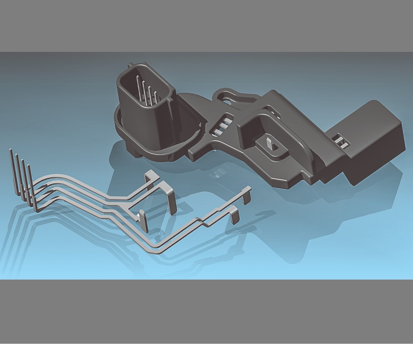
Case 3: Two parts of overmolded glass-filled nylon 612 are produced in 20 sec.
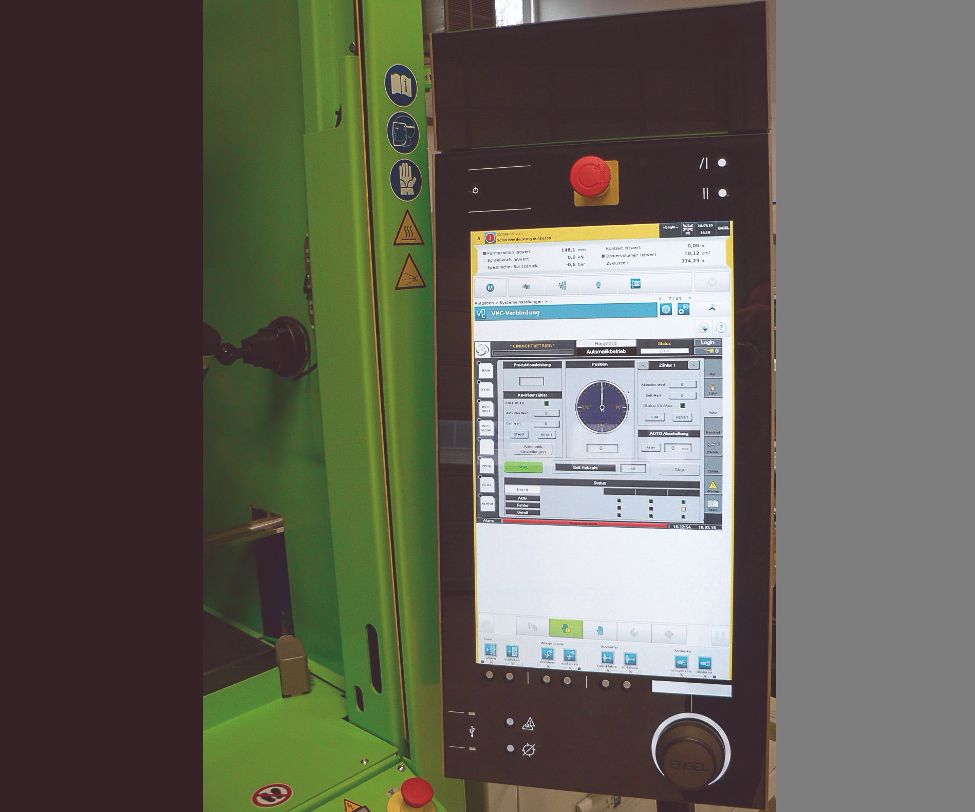
All elements of the hybrid molding cell can be monitored and controlled from the Engel CC300 injection press controller.


Overmolding of plastic onto metal electronic components is used in various industries, including automotive, appliance white goods, telecommunications, medical technology, and aerospace. Such metal/plastic “hybrids”—for example, switches, connectors and sensors—require highly integrated production cells, most of which are dedicated to one specific product. But today, as life cycles are becoming shorter, manufacturers are looking for more flexible production options. Hence, there is a trend to modular plant layouts, according to sources at Engel Austria, parent of Engel Machinery Inc., York, Pa. (engelglobal.com). One such layout is a highlight of Engel’s exhibit at NPE2018 in Orlando, Fla., next month.
LINEAR VS. RADIAL SYSTEMS
Engel identifies two basic types of production cells for teletronic hybrid molding—linear and radial. Linear machine systems produce hybrid components on a continuous strip, as illustrated above. The strip, or leadframe, is the product carrier through the line. The injection molding machine is located between, and synchronized with, the other production modules. The advantage of this approach is quick and simple operation using minimum floorspace. No other handling systems or robots are required. At the end of the line, the final parts are stamped out or coiled on a reel.


Radial machine systems are used if no connections to a carrier are compatible with the product design, or if the metal parts are much smaller than the plastic component. Here, the injection machine is used with a two- or three-station rotary indexing table, which allows loading and unloading the components simultaneously with overmolding. The setup is normally with a preparation and loading stage on the left and an additional processing stage on the right for post-molding steps such as inspection, labeling, or assembly. Use of servo infeed systems, with multiple x/z axes available, help make the setup very clear and easily accessible. If required by the application, SCARA and six-axis articulated robots can also be used.
Engel has partnered with MMS Modular Molding Systems of Austria, a specialist in turnkey production lines for metal/plastic hybrids. MMS offers a universal software and control system with various sub-programs for different processing modules that can be activated
when the process and product require them. The software is operated centrally from a 19-in. touchscreen monitor. For larger cells, two or three screens can be placed in strategic positions. The MMS software has been integrated with Engel’s CC300 machine controller, so that the entire system can be displayed and operated from the injection press. Additional software for cameras or laser marketing is integrated as a separate module. For setup and manual operation, there is also a handheld terminal with electronic hand wheel.
Engel and MMS collaborated in the following real-world examples of three systems that have been used in commercial production.
CASE 1: THERMAL SWITCH HOUSINGS
This example of a linear system will be running live at NPE2018 next month. It produces a continuous strip of thermal switch housings used to monitor electric motors in cars or home appliances. Typically, such switches are produced in a complex, multistage process with the metal components punched and overmolded at different locations. Instead, this continuous line greatly reduces logistics. From punching out the contacts to inspection and labeling of ready-to-use electronic components, all work steps are fully automatic. Thin brass sheet for the carrier plate is fed from a reel and pre-punched in an operation that includes servo-electrically tapping a thread into the brass substrate.
Next, the carrier plates are overmolded with glass-filled nylon in an Engel insert 60V/35 (38.5-ton) vertical injection machine. In-process quality control includes camera inspection plus high-voltage testing integrated into the tool, guaranteeing 100% short-circuit inspection. For seamless traceability, good parts are laser marked before the sprue and carrier tabs are removed and the components are separated from the belt. Eight ready-to-use switches leave the cell every 20 sec.
Thanks to the modular design of the MMS systems, additional processing units can be integrated, such as resistance testing, laser welding, riveting, assembly, or cleaning of the parts. All these extra operations can also be monitored and controlled via the CC300 control of the insert molding press.
CASE 2: FOUR-PIN PLUGS WITH LSR SEAL
This example of a radial production system produces eight parts every 24 sec. It starts with a pre-punched and galvanized strip of copper/tin alloy, selectively gold plated in the electrical contact area and tinned in the soldering area. The strip is unwound from a coil using an automatic swivel winder (Module 1). The swivel winder makes it possible to position a second coil in standby so as to reduce setup time. The strip can be changed very quickly without thermally degrading the plastic held in the melt state during changeover.
The servo-electric gripper feeder (Module 2) feeds the flat strip into the system. The linear servo motor ensures very high accuracy. In the subsequent cam-controlled punching and bending (Module 3), connecting webs are separated and the contacts are bent. The following joining and sealing step in the injection mold requires high precision, making it advantageous to feed the parts on a strip. This method also avoids potential damage in a bowl feeder. Bending the parts directly before overmolding allows compensation for internal stresses and hardness variations in the strip.
Still in the punching tool, the parts (four contacts × eight cavities = 32 per shot) are separated and inserted into the injection mold (Module 6) using an Engel easix SCARA robot (Module 4). The Engel insert 60V/35 XS injection press (Module 5) has two lower mold halves on the turntable, so that insert placement and overmolding can occur in parallel. The eight-cavity injection mold is equipped with four hot-runner nozzles and a sub-distribution manifold for the 30% glass-filled PBT material.
The eight overmolded components are demolded by an Engel viper 6 linear robot (Module 7). Directly beneath the gripper is a camera (Module 8) checking that all cavities were completely filled and that all parts and sprues were demolded. On a conveyor belt, sprues and rejects are automatically separated.
The viper 6 then places the parts on a turntable that acts as a buffer for the downstream processes. The parts are then transferred by the viper 6 to a rotary indexing table for assembly and testing. That table (Module 9) has eight processing stations:
• Station 1: Inserting and positioning the parts.
• Station 2: Free.
• Station 3: Feeding the LSR sealing elements. The parts are fed in the correct position, picked up by a servo handling system, and assembled.
• Station 4: Camera inspection to check the sealing element.
• Station 5: Camera performs optical “wobble circuit test” of the four contacts in the plug.
• Station 6: Test station to check pin height via 3D laser sensor.
• Station 7: Removal of finished parts.
• Station 8: Free.
Finished parts are transferred to an MMS tray server by a servo handling system (Module 10). In the tray server (Module 11), preformed blister trays are automatically unstacked and cleaned with a blast of ionized air (Module 12) before being filled. Reject parts and test parts are stored separately. The filled blisters are stored in magazines. Safety circuits allow loading and unloading of blister trays during production.
CASE 3: CONTACT ELEMENTS
This second radial production cell produces two parts every 20 sec. It consists of three units: a rotary table for preparing the contacts, an Engel insert rotary vertical injection machine, and a blister-tray packaging unit. To the left of the injection press, the pre-punched and galvanized strips of tin-plated copper are fed to a rotary-table unit. Due to the complexity of the conducting paths and restricted space in the component, the leadframe must be divided into two strips. Two feeding and bending stations are identically constructed. The tapes are unwound from a swivel winder while rewinding the paper liner that protects the contacts.
The tapes are fed into the system by MMS servo-electric gripper feeders. In the subsequent cam-controlled punching and bending module with six independent slide units, the contacts are cut free, bent and separated. The components are then transferred by a moving plate and two servo handling systems to a workpiece carrier. The two leadframes are positioned precisely for the later injection overmolding step.
But first, the contacts are bent in the third station on the rotary table. This is done directly in the workpiece carrier by a cam-controlled bending module, which ensures that the contacts in the connector area are bent exactly 90°; it can be adapted to different metal material properties. High precision is required because the upper half of the mold has to thread the contacts. Before transferring the bent contacts, their geometry is checked by a camera in the fourth processing station. In the fifth station, the contacts are picked up by an Engel easix articulated robot and placed in the injection mold. As soon as two components are placed, the table of the injection machine rotates and the components are overmolded with 30% glass-filled nylon 612.
A second easix articulated robot demolds the parts and places them in a blister tray. Having two articulated robots right and left of the injection machine provides optimal access to the mold area, and the parallel operation of the two robots reduces cycle time. The blister tray is provided by an MMS tray server, and the filled trays are stacked for removal.


Related Content

Best Methods of Molding Undercuts
Producing plastics parts with undercuts presents distinct challenges for molders.
Read More
How to Mount an Injection Mold
Five industry pros with more than 200 years of combined molding experience provide step-by-step best practices on mounting a mold in a horizontal injection molding machine.
Read More
How to Get Rid of Bubbles in Injection Molding
First find out if they are the result of trapped gas or a vacuum void. Then follow these steps to get rid of them.
Read More
Understanding the ‘Science’ of Color
And as with all sciences, there are fundamentals that must be considered to do color right. Here’s a helpful start.
Read MoreRead Next

Understanding Melting in Single-Screw Extruders
You can better visualize the melting process by “flipping” the observation point so that the barrel appears to be turning clockwise around a stationary screw.
Read More
Why (and What) You Need to Dry
Other than polyolefins, almost every other polymer exhibits some level of polarity and therefore can absorb a certain amount of moisture from the atmosphere. Here’s a look at some of these materials, and what needs to be done to dry them.
Read More
Troubleshooting Screw and Barrel Wear in Extrusion
Extruder screws and barrels will wear over time. If you are seeing a reduction in specific rate and higher discharge temperatures, wear is the likely culprit.
Read More