
New Runner-Design Concept Boosts Quality & Productivity
Why 'naturally balanced' multi-cavity molds sometimes refuse to fill evenly is a mystery that eluded solution—until now. A simple concept called the MeltFlipper allows molders to increase cavitation and maximize output of quality parts.


MeltFlipper inserts use changes in runner elevation to "flip" the melt orientation by 90°, eliminating asymmetrical distribution of hotter and cooler melt to diverging runner branches.
Fig. 1—High shear and frictional heating near the outer wall of a runner channel lower the viscosity in this region. This is the root cause of filling imbalances.
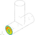
Fig. 2—FIDAP analysis output shows the asymmetrical temperature distribution in a secondary runner branch as a result of frictional shear heating and laminar flow.
Fig. 3—Distribution of melt laminates into a secondary runner. The symmetrical, annular flow pattern in the primary runner becomes asymmetrical in the secondary runner, with hotter, high-shear laminates following one side of the channel wall, and cooler laminates flowing along the other.
Fig. 4—Unbalanced flow in typical "naturally balanced" runners. Red cavities typically fill first, causing variations in size, shape, and mechanical properties. Example E show similar effects in a single cavity with multiple gates.
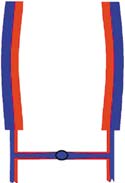
Fig. 5—Unbalanced flow causes mirror-image warpage patterns in a four-cavity mold.
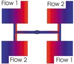
Fig. 6A—Unbalanced flow in conventional four-cavity layouts creates a diagonal pattern of similar parts.
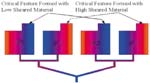
Fig. 6B—Unbalanced flow in four-cavity parting-line injected tool creates similar parts in every other cavity.
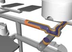
Fig. 7—MeltFlipper changes runner elevation to reorient the division of the melt laminates from side-to-side to top-to-bottom, so that similar"slices" of melt laminates are distributed to each runner branch.
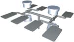
Fig. 9—Typical MeltFlipper insert arrangement in a traditional H-pattern eight-cavity mold.
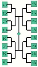
Fig. 10—Cavity layout of Avaya's mold and part-weight distribution before and after application of the MeltFlipper.
Nowadays, injection molders are under increasing pressure (pun intended). Demands for tight tolerances, near-zero rejects, and ever-lower cost that were once limited to automotive and medical jobs are now common even for molders of consumer products. Molders have often responded by limiting themselves to molds of low cavitation because they are easiest to balance naturally. But low cavitation requires more molds, more machines, more floor space for the machines, and more people to run them. To remain competitive in a global marketplace, cost can only be reduced by producing parts faster with more consistency and less scrap. If higher-quality parts can be produced from an eight-cavity mold rather than a four-cavity tool, or from 16 cavities instead of eight, cost savings and greater customer satisfaction will follow. The question is how to get there.
The basis of the solution came to me in 1997 when I was wrestling with the issue of mold-filling imbalance. For years, I had observed imbalances in what have always ben called "naturally balanced" runners. A member of mycomputer-aided-engineering consortium at Penn State Erie was encountering just such a problem. His eight-cavity mold was "naturally balanced," and yet the parts from the mold's inner cavities were consistently heavier than those made in cavities farther from the sprue. Tight weight tolerances for this part didn't allow for such variation, and at nearly $20/lb, material waste had to be held to a minimum.


I first blamed the two usual suspects: cooling variations created by higher thermal load of the plastic parts near the center of the mold, and plate deflection within the mold. These standard scapegoats had served industry well for years. But this mold had a well-designed cooling system that provided increased cooling to the inner cavities. One look at the mold's rigid support columns and the parts' thick walls told me plate deflection wasn't the problem either.
I started thinking about runner systems. I started thinking about the laws of physics and everything I knew about laminar flow. Then I started retracing the runner from the gate back down to its first branch.
The end of symmetry
Plastics exhibit a laminar (or streamline) flow through a runner, so the melt is divided into many concentric layers or "laminates" that have different shear and temperature conditions. Regardless of flow rate, shear is greatest near the wall of a runner channel and lowest—or zero—at the center (see Fig. 1). Melt viscosity will be significantly lower in these high-shear laminates than in the middle of the runner flow.
Additionally, high shear near the runner wall can create significant frictional heating in the outer laminates. Sophisticated 3D mold-filling simulations have shown these outer laminates to be as much as 100° C hotter than the laminates in the center of the runner channel. Laminar flow and the low rate of heat transfer between laminates maintain the distinct layered structure as the melt proceeds along the runner.
Highly sheared, hotter, less viscous material flows in an annular ring along the channel walls surrounding low-shear, cooler, more viscous laminates flowing in the center of the channel. Sometimes unusually low-shear conditions in a cold-runner mold can cause the outer laminates to be cooler than the inner laminates. But under any circumstances, there will be a difference in the melt's condition between these laminates.
Looked at in cross-section, the pattern of flow laminates across the runner is initially symmetrical. But when the flow splits at a branch, that symmetry is lost, and filling imbalance begins.
The computer doesn't lie
I asked Dr. Jack Young, a mechanical-engineering colleague at Penn State Erie, to help me make a computer analysis of an eight-cavity test mold I was having built. With assistance from a student researcher and Fluent Inc.'s FIDAP fluid-dynamics analysis software, we needed more than three months to develop the required model and complete an analysis.
We could have modeled a runner in five minutes using any of the commercial injection molding software packages. But we needed to start from scratch in order to overcome the limitation of the one-dimensional solution techniques used for runner analysis in these programs. Without recognizing the shear-induced imbalance created in a branching runner, developers of injection molding simulation software have used one-dimensional analysis to simplify modeling and provide faster calculations. This short cut cannot predict the asymmetrical conditions that develop in a branching runner. Though I am still a huge fan and user of injection molding simulation, I recognize the limitations of current programs in designing runners and am working with CAE providers to overcome this problem.
Our analysis was able to pick up the asymmetrical temperature distribution in the secondary runner (Fig. 2). However, the result was not what I expected: 70% of the flow was going to the inside cavities, and only 30% to the outside. I was sure this degree of imbalance was too large to be true.
When our test mold arrived, I found that the computer hadn't lied: In several tests with different resins and injection rates, the best balance we could produce was 65% of flow to the inside cavities and 35% to the outside. At worst, 95% of the material flowed into the innermost cavities.
Can symmetry be restored?
Our computer simulation and test mold proved that the imbalance developed in the standard geometrically balanced runners resulted from the shear variations across the flow channel. The symmetrical nature of the flow—with hotter, highly sheared laminates near the outside wall and cooler, less-sheared laminates in the center—became asymmetrical when it split at a branch (Fig. 3).
After the branch, flow velocity, shear rate, temperature, and viscosity across the branching runner were redistributed, with high-shear, hotter laminates following one side of a branching runner, and low-shear, cooler laminates concentrated on the other side.
In a typical eight-cavity, H-pattern mold, the flow will split again, with most of the high-shear, hotter, low-viscosity material flowing to one cavity on each tertiary runner section, which therefore fills first. We now refer to this as Flow #1, or the dominant flow. The cavities it fills will often flash while other cavities are still filling. Parts formed from these cavities will normally be heavier and larger than those from other cavities. Additionally, they will shrink and warp differently from other cavities, and will have different mechanical properties as well. In fact, shear effects on mold-filling imbalance may dwarf all previously suspected causes of product variations in multi-cavity molds.
Predicting which cavities will receive Flow #1 in a multi-cavity mold is as simple as following the outside edges of the runner system from sprue to cavity. Similar divisions occur in a single cavity with multiple gates (Fig. 4). Place a pencil against the side of the primary runner in a mold and drag the pencil along, continuing through all of the branches, until it gets to a cavity. This is the cavity that will be filled by Flow #1.
In a normal eight-cavity mold, two flows will result: Flow #1 develops from the high-shear material and Flow #2 from the low-shear material. In a 16-cavity mold there will normally be four flows; 32 cavities will result in eight flows; 64 will result in 16 flows, and so on. Each of these flows produces parts that are formed under different conditions.
In molds with four cavities (and sometimes with only two), the high-shear laminates will end up on opposite edges of parts formed in different cavities, potentially causing mirror-image warpage in the molded parts (Fig. 5). In standard four-cavity molds, adjacent cavities will be different from one another. In conventional sprue-fed, four-cavity molds, this will result in like parts being molded in cavities positioned diagonally to each other (Fig. 6A). In four-cavity, parting-line-injected molds with an in-line cavity arrangement, like parts will be molded in every other cavity (Fig. 6B). Again, one can use the technique of running a pencil along the edge of the primary runner to determine where Flow #1 will end up.
Face the facts
"But we don't have a filling imbalance." I don't know how many times I have heard these words. My response is that nearly every mold using conventional geometrically balanced ("naturally balanced") runners and having two or more runner branches does indeed have a filling imbalance.
It's simple to prove: Walk into any plant running a mold with this type of runner, eliminate hold and pack pressure, and reduce the shot size until the best-filling cavities are about 70-80% full. The imbalance usually will be visually obvious. It can be quantified by weighing the parts formed from Flow #1 and comparing their weights to those of any of the other cavity groups.
Hot-runner suppliers have asserted that good mold balance can be demonstrated by comparing weights of fully packed parts. Yet even if the brute force of the molding machine equalizes the part weights to within a fraction of a gram, differences in filling and packing can still result in variable shrinkage, warpage, and mechanical properties. Our short-shot test reveals imbalances that are masked but not eliminated in a fully packed shot.
Companies are so conditioned to believe the conventional wisdom about "naturally balanced" runners that they ignore the factor of runner design as a possible source of their filling problems or product variations. They will blame the mold builder, material supplier, equipment manufacturer, or the position of the stars before they question the runner.
For decades, so much money, time, and effort have been directed at improving product consistency through better plastic materials, SPC/SQC methods, finer control of injection molding machines, and precision machining of injection molds. Yet none of these have any ability to influence the large variations that regularly occur between cavities within a single shot.
The shear-induced imbalance from a runner creates variations in shot size, fill rate, and fill pressure between cavities that can easily exceed 20%. In an eight-cavity mold, when the Flow #1 cavities fill, other cavities may be only 70-80% full. At the instant the Flow #1 cavities fill, injection rate in the later-filling cavities will double, and the melt pressure in Flow #1 cavities will instantly spike, while pressure at the flow front in the other cavities is still zero.
If variations of this magnitude were created by a molding machine, tooling, or resin material, they would be unacceptable and their supplier would be out of business. Yet injection molders live with these variations every day. I love microprocessor-based, multi-zone, living-color, fingertip-digital-input machine controllers as much as anyone. But they can't fix the flow imbalance or the resulting variations in molded parts.
The MeltFlipper is born
It turns out that it isn't necessary to eliminate the asymmetry developed at a runner branch—it only needs to be repositioned. Picture a runner that branches horizontally from side to side. The melt therefore divides along a vertical axis at the branch. If, subsequently, the melt in each branch could somehow be rotated or flipped so that its symmetry was no longer top to bottom, but side-to-side, at the next split the flow fed to each cavity would be of equal temperature, pressure, and viscosity. This would be the true "naturally balanced" runner system that the industry always thought it was working with.
One method to reorient the melt is to add an elevation change within the runner that causes the melt to literally "flip," hence the name MeltFlipper. It counteracts the asymmetrical, side-to-side variation of flow laminates occurring at runner branches, thus ensuring that each mold cavity receives an equal proportion of the varied melt conditions, and that cavities fill at approximately the same time. Located at the intersection of branching runner sections in a standard H-pattern runner, the MeltFlipper repositions the side-to-side flow variations by rotating the melt circumferentially about 90° at the first branch (Fig. 7).
Instead of allowing the hotter, more shear-thinned laminates in the primary runner to follow the inside wall of the secondary runner, the MeltFlipper diverts these laminates to the bottom of the secondary runner. The cooler, more viscous laminates from the center of the flow, which normally transfer to the opposite surface of the secondary runner, are repositioned to the top of the secondary runner.
When the melt splits again at the tertiary runner, the laminates entering the runner branches will be proportionally the same, with equal amounts of high-shear and low-shear laminates. Flow to all the mold cavities will be balanced. For molds where there are three or more runner branches, as in the case of standard 16- or 32-cavity layouts, the MeltFlipper can be applied to the intersection of primary and secondary runners to achieve the desired melt positioning at the next branch, and again at the intersection of tertiary and quaternary runners, and so forth.
The tip of the iceberg
With this new understanding of shear-induced imbalances in runners, a gremlin that has haunted us for years has been unveiled, as have significant new opportunities. Over the five-plus years that I have focused on this issue, I have seen hundreds of applications that were once thought to be molded under ideal conditions and yet experienced problems caused by the old mold gremlin, filling imbalance. In addition to the production problems created by filling imbalances, we have found that there can be significant property variations between parts formed in the various cavity groups. By recognizing the various flows in a mold, one can more quickly separate product variations created by mold steel and process conditions from those caused by runner imbalance. The resulting faster commissioning of new molds can pay for the MeltFlipper even before production starts.
The biggest advantage of the MeltFlipper is that molders can potentially double or quadruple production using higher cavitation molds while maintaining cavity-to-cavity consistency. The MeltFlipper resolves typical problems resulting from flow imbalances, including inconsistent packing, part weight, and size; warpage; increased clamp tonnage; flash; short shots; and even material degradation with sensitive resins like PVC. The MeltFlipper also offers potential for controlling part warpage and the distribution of gas in gas-assist molding.
The MeltFlipper can be adapted to nearly any runner profile and imposes virtually no restrictions on flow. Because it can be accommodated in an insert as small as 15 mm diam., the MeltFlipper readily retrofits to existing molds (Fig. 9). Finally, the technology is very tolerant of process variations and can be applied to hot-runner, cold-runner, and stack molds.
Though most of our experience with the MeltFlipper is in cold runner molds, the same technology works with hot runners. Of particular interest is a new design variant we developed specifically for stack molds that are fed with hot runners. In stack molds, the cavities along the parting plane nearest the injection unit normally fill first. The stack mold requires a new runner design that can balance filling not only along a single plane, as with conventional hot-runner molds, but between the multiple parting planes.
New kind of flow analysis
Our major challenge in applying the MeltFlipper technology has been the lack of a user-friendly, "true 3D" flow analysis for runners. Hot-runner systems are complicated to experiment with, expensive, and not easily adjusted if a desired balance is not achieved. These systems require a well-developed 3D flow analysis for effective runner design. Not finding what we needed in the marketplace, we are developing our own with funding from the State of Pennsylvania's Ben Franklin Technology Program.
The new product, RunnerFlow 3D, uses optimized 3D filling analysis to provide the means to automatically design the required MeltFlipper features for a particular mold. Rather than simply outputting flow-analysis results, the new program is being developed to provide actual designs of the runner incorporating the MeltFlipper features, along with guidelines regarding its application. We plan to make this software available via the Internet to licensees of MeltFlipper technology. The program will use simple templates that will eliminate the need for sophisticated modeling and meshing by the user.
Success at Avaya
Lucent Technologies (now called Avaya, Inc.) was one of the first national corporations to see the MeltFlipper's potential for making high cavitation the rule, rather than the exception. Jay Van Roy, a process engineer in Avaya's facility in Omaha, Neb., first became intrigued by the MeltFlipper from a research paper I presented at an SPE ANTEC meeting in 1998. He decided to put the MeltFlipper to the test.
"I had a new tool coming out that I would have typically built as an eight-cavity mold," Jay told me recently. "I wanted to test it with 16 cavities, using the MeltFlipper to prove to myself that the claims made for it were true. I'm always looking for ways to increase the process window, decrease set-up time, and improve quality."
Jay admitted he was skeptical at first, particularly because the part he tested weighed only 0.13 g and had an intricate geometry and thin walls. The test mold was a naturally balanced "H" pattern, and the material was a PC/ABS blend. "Naturally balanced, the variation in part weight was 31%," Jay said. "With the MeltFlipper, the variation decreased to 4%, and I attribute most of that to steel variation in the mold (Fig. 10). We monitored cavity pressure in the mold, and it was more consistent with the MeltFlipper, too."
Avaya has since purchased a corporate license to use MeltFlipper technology on multiple molds. Jay says, "The big thing for us is the cost savings. When I can go from eight to 16 cavities, the cost is cut pretty close to half because I'm making one less mold and using one less machine."
Other national companies using MeltFlipper technology include Osram Sylvania, Lear Corp., Nypro, Lord Corp., Emerson, Summit Polymers, 3M, Loranger Mfg., and General Motor's Packard Electric Div.
John Beaumont, president and CEO of Beaumont Runner Technologies, Inc. in Erie, Pa., is also an associate professor of plastics engineering at Penn State Erie. He is a co-founder of the University's Plastics Technology Deployment Center and founder of its Computer Aided Engineering Consortium. For more information, call (814) 899-6390, visit www.meltflipper.com, or write in 81 on Reader Service Card.


Related Content

Fakuma 2023: More Details on New Machine Line
Wittmann Battenfeld has released more details on the new EcoPower B8X debuting at Fakuma (October 17-21; Friedrichshafen, Germany), which it previously announced.
Read More
Medical Grade Injection Molding Machine Line is Cleanroom Ready
JSW America says the J100ADS-110U medical grade molding machine has been optimized to prevent dust, rust and other contaminants.
Read More
Fakuma 2023: Wittmann Battenfeld Expands All-Electric Line, Direct-Current Capabilities
Wittmann Battenfeld will introduce the new EcoPower B8X injection molding machine line and show direct current as an energy source for a concept machine that will power its own robot.
Read More
Completely Connected Molding
NPE2024: Medical, inmold labeling, core-back molding and Industry 4.0 technologies on display at Shibaura’s booth.
Read MoreRead Next

Advanced Recycling: Beyond Pyrolysis
Consumer-product brand owners increasingly see advanced chemical recycling as a necessary complement to mechanical recycling if they are to meet ambitious goals for a circular economy in the next decade. Dozens of technology providers are developing new technologies to overcome the limitations of existing pyrolysis methods and to commercialize various alternative approaches to chemical recycling of plastics.
Read More
Lead the Conversation, Change the Conversation
Coverage of single-use plastics can be both misleading and demoralizing. Here are 10 tips for changing the perception of the plastics industry at your company and in your community.
Read More
Why (and What) You Need to Dry
Other than polyolefins, almost every other polymer exhibits some level of polarity and therefore can absorb a certain amount of moisture from the atmosphere. Here’s a look at some of these materials, and what needs to be done to dry them.
Read More