
Part 1: The Basics of Tapered Interlocks
Various types of interlocks are available to molders. Here, we discuss the oldest and most common types of interlocks—those with a tapered or angular shutoff.


When selecting the type, size and location of interlocks for an injection mold, base your decision on what you need them to do. They can align any two mating mold plates or component parts. They can protect fragile shutoffs. Or they can provide support to prevent deflection. Various types of interlocks are available to molders. None of them are the best at performing all three functions—align, protect and support. This article will discuss the oldest and most common types of interlocks—those with a tapered or angular shutoff.
Let’s first discuss why every mold needs interlocks. There is a clearance between leader pins and their bushings of 0.0015 to 0.0025 in., and that’s when they are brand-new. Unless you jig-grind the bore holes for the pins and bushings, there is going to be a slight misalignment due to the milling machine’s positional and angular capabilities.


Now factor in the inevitable wear of the bushings, especially if they are made of relatively soft aluminum bronze. Over time, the bushing bore holes can also elongate. I’ve seen bushings that were so loose, set screws were installed from the sides of the mold to prevent them from falling out.
The molding machine itself adds to the need for interlocks. The platens are never absolutely parallel. They too have bushings, and support pads that wear, which allow the platens to tilt. The older the machine, the more the tilt. When a mold without interlocks is hung in a machine, one half of the mold is likely to be lower than the other by an amount equal to all of these combined clearances.
Bottom line: Leader pins are nothing more than a preliminary method of roughly aligning the two halves of a mold. How many times have you heard the end of a leader pin bump the entrance to its bushing when the mold closes? If a mold does not have any interlocks to precisely align the two halves, there is a strong likelihood that the molded part will have an uneven wall thickness. That might not be an issue with a thick walled part, but on a thin walled part it will radically change the fill pattern, which can lead to all sorts of problems.
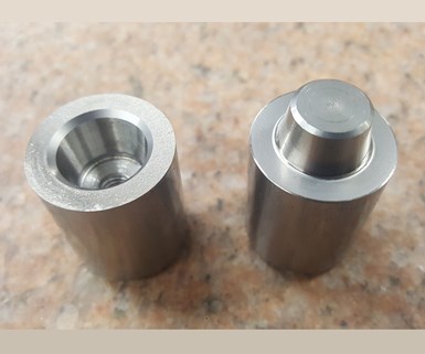
FIG 1a: One of the two types of off-the-shelf interlocks with tapered or angled shutoff—the conical type.
Types of Tapered Interlocks
There are two types of off-the-shelf interlocks with a tapered or angled shutoff: conical (Fig. 1a) and rectangular (Fig. 1b). The angle of the taper is typically 10° per side in the U.S., 15° in Europe, and 5° in Asia. These interlocks align two mating components only when the mold is fully closed and their angled faces are touching. That is their primary function—alignment. Conical interlocks align plates or components in a full 360° about their center axis. One common misconception is that rectangular interlocks only align plates or components in one direction. That’s not true. Even though the two plates are free to slide parallel to their length, it is their length that also prevents any angular or rotational misalignment.
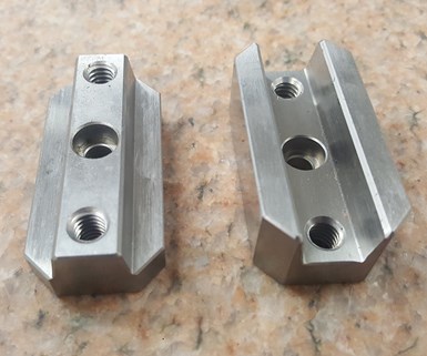
FIG 1b: Rectangular interlocks are the second type of off-the-shelf interlocks with tapered or angled shutoff.
Rectangular interlocks have a lot more surface contact area than conical interlocks, as shown in Table 1. They are also anchored more securely in the mold. That is why they are the best at overcoming misalignment, and they will last longer than any other type.
Another misconception is that conical and rectangular interlocks do not provide any protection to mold components that have an angled shutoff prior to the mold being fully closed. That’s not entirely true. As long as the shutoff angle of the mating components is greater than the interlock’s shutoff angle, the components are protected. That is why at least two mold-component suppliers (one domestic and one off-shore) offer conical interlocks with a 1°, 3°, 5° or 10° taper per side. And one off-shore supplier offers rectangular interlocks with 1°, 3° or 5° taper per side.
Technically, any mating steel components that have an angle of 7° per side or less is called a self-locking taper. However, the amount of locking or holding power depends on several factors, such as the coefficient of friction between the mating parts, the surface roughness, the hardness of the materials, the presence of any lubricants and the force applied to them. In injection molds there is a good possibility of having a locking issue with an angle between 1° and 3°, but unlikely that you will have one with an angle greater than that.
If you use interlocks with a shallow taper, keep in mind that the amount of misalignment cannot exceed the length of the opposite side of the angle, as opposed to the length of the adjacent side or the hypotenuse. Otherwise, the top of the male and female halves will hit each other, instead of engaging each other.
Thermal Expansion
Conical interlocks have one significant drawback. If for any reason one half of the mold is hotter than the other, the two mold halves will expand different amounts and the interlocks will be out of alignment.
The coefficient of thermal expansion for carbon steel is 6.7 × 10⁻⁶ in./in.-oF. The amount two interlocks will be misaligned is equal to 0.0000067 × the distance between the locks × the temperature difference between the mating plates. Therefore, it is important to take into consideration how far apart you mount conical interlocks, and what the expected temperature difference might be between the two halves of the mold.
To show you how important this is, let me give you a scary example. Figure 2 shows a tapered interlock that has shifted just 0.0005 in. due to a difference in plate temperatures. Theoretically, this very slight shift causes an interlock with a 10° taper to separate at the parting line by about 0.0034 in. That’s certainly more than the depth of any cavity vent.
Table 2 shows that interlocks don’t have to be very far apart and the temperature differential doesn’t have to be that great to get more than this 0.0005 in. of thermal expansion. Fortunately, these are theoretical values. In the real world the female half will expand, the male half will compress, and the pockets in the plates will “give.” But it takes clamp tonnage to do that. The greater the amount of thermal expansion, the greater the amount of tonnage required to overcome it. When a mold is flashing, but it blued off fine on the bench, thermal expansion could be the root cause of the problem.
In contrast, if a mold does not have a thermal expansion issue—meaning both halves of the mold are the same temperature—regardless of what the ambient temperature is, the farther the interlocks are spaced apart from each other, the more accurate the alignment will be.
Mold Design
The female half of an interlock should always be mounted on the hotter side of the mold, and the male half on the cooler side. Due to hot runners, hot bushings and part-sticking problems, the hotter side of the mold is typically the injection side. If the male half gets significantly warmer than the female half, the fitted height increases, as does the rate of wear and the force required to close the mold.
Since interlocks are tightly fitted into the mold, an easy method of removal should always be considered. This usually isn’t a problem with off-the-shelf interlocks, but if you are making your own, pry slots, jack-screw holes, punch-pin holes, or through pockets are required.
Over time, interlocks may enlarge their bore or pocket due to heavy side loads. Some moldmakers grind the outside diameter of conical interlocks or the sides of rectangular interlocks by 0.005 to 0.010 in. during the initial installation. If a bore or pocket elongates, it can be skim-cut, or re-faced, and a new set of interlocks can be installed without concern about them being loose. This is a good insurance policy if you don’t have the room available to go to the next larger size.
One advantage of conical interlocks is that they are relatively easy and inexpensive to install. Preferably, they should be installed by line boring or partial line boring by clamping two or more plates together. Blind boring both halves of a conical interlock should be avoided, as they are the most difficult to align. In very thick plates, it is better to line bore the holes and add a hardened spacer behind the lock to achieve the necessary length.
A few mold-component suppliers offer both male and female conical interlocks with a counterbore on the front face. This allows for “face-mounting,” or installation from the parting line. The advantage of this method of installation is that it frees up room underneath the interlock for water lines or other mold components.
Some suppliers offer cylindrical interlocks with rectangular mating faces, as opposed to a conical mating face. These hybrid interlocks are easy to install and provide the same benefits that rectangular locks do, but they have to be precisely keyed to prevent any radial misalignment.
Speaking of unique designs, an old friend recently told me about one of his molds not having room to install any interlocks. So he made custom leader pins that looked like step pins, but instead of the 90° sharp inside corner at the step, there was a 10° per side transition from the small diameter to the large diameter. The leader pins mated with custom bushings that had a 10° conical seat. He got his alignment despite the lack of real estate in the mold.
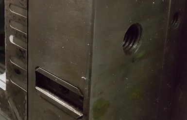
FIG 3a: Correct direction to install a rectangular interlock.
Location
Rectangular interlocks should be installed perpendicular to the sides of the mold, preferably on the centerlines, forming a “plus sign” configuration (Fig 3a). They should never be installed parallel to the sides of the mold, as shown in Fig. 3b. Although this recommended design takes up quite a bit of valuable space, it provides trouble-free alignment regardless of how much thermal expansion there might be.
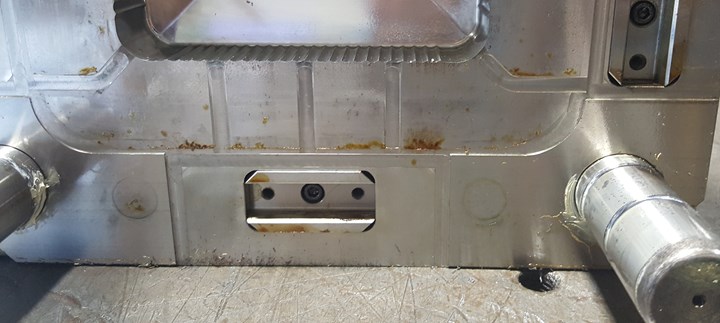
FIG 3b: Incorrect direction to install a rectangular interlock.
Why should rectangular interlocks be installed on the centerline of the mold? When they’re installed on the centerline, it doesn’t matter if the entire mold expands or just one half of the mold expands. The interlocks will allow them to expand and still keep them aligned. If you were to install the interlocks off-center, when one half of the mold expands more than the other, the interlocks won’t line up and there will be a problem. This is not to say that it’s mandatory to install rectangular interlocks on the centerlines of a mold. Quite often, an eyebolt hole or a water line is in the way. Just keep in mind that the farther they are installed from the center, the greater the risk of having an issue of differential thermal expansion.
All interlocks function best if they are mounted directly in the cavity and core inserts, rather than in the plates. Cavity and core pockets are usually relieved and sometimes there is not a lot of bearing surface. The inserts may be allowed to “float” a little, even though the plates are aligned. When interlocks are installed in the inserts, their alignment is guaranteed. If you can’t install them in both the cavity and core inserts, installing one in a plate and the other in an insert is better than both in the plates.
If a part has an opening or window in it, a male conical interlock can be mounted in the shutoff opening on the top of the core, and a female interlock in the bottom of the cavity. This method of interlocking works extremely well at preventing core shift.
Interlocks mounted between a stripper plate and a core plate work well at protecting the angled shutoffs. As long as the taper of the interlock is less than the taper of the stripper plate shutoff, the interlocks will engage before the stripper plate shutoffs do.
About the Author
Jim Fattori is a third-generation injection molder with more than 40 years of molding experience. He is the founder of Injection Mold Consulting LLC, and is also a project engineer for a large, multi-plant molder in New Jersey. Contact jim@injectionmoldconsulting.com; injectionmoldconsulting.com.


Related Content

Why Shoulder Bolts Are Too Important to Ignore (Part 2)
Follow these tips and tricks for a better design.
Read More
Why Shoulder Bolts Are Too Important to Ignore (Part 1)
These humble but essential fasteners used in injection molds are known by various names and used for a number of purposes.
Read More
Hot Runners: How to Maintain Heaters, Thermocouples, and Controls
I conclude this three-part examination of real-world problems and solutions involving hot runners by focusing on heaters, thermocouples, and controls. Part 3 of 3.
Read More
Back to Basics on Mold Venting (Part 2: Shape, Dimensions, Details)
Here’s how to get the most out of your stationary mold vents.
Read MoreRead Next

Understanding Melting in Single-Screw Extruders
You can better visualize the melting process by “flipping” the observation point so that the barrel appears to be turning clockwise around a stationary screw.
Read More
Processor Turns to AI to Help Keep Machines Humming
At captive processor McConkey, a new generation of artificial intelligence models, highlighted by ChatGPT, is helping it wade through the shortage of skilled labor and keep its production lines churning out good parts.
Read More