
How to Prevent Nozzle Tip Leaks, Part 2
Your very costly mold in that very expensive press is relying on the performance of a $20 nozzle tip that no one ever checks, and has a high probability of not doing its job. Stop learning from your mistakes and start learning how not to make them.


A common cause of leakage between the machine nozzle tip and the sprue bushing is incompatible radii. I took a brand-new sprue bushing from a reputable mold-component supplier and three brand-new machine nozzle tips from three different mold-component suppliers and blued them off, as shown in Fig. 1. One of the nozzle tips seated on the outer perimeter of the sprue bushing; one seated in the middle; and the third seated in the center.
The one that seated on the outer perimeter has a very good chance of blowing the carriage back and allowing material to leak out. The level of precision on machine nozzle tips is not just highly suspect. It’s a flat-out crap shoot. Maybe that’s why they are so inexpensive. Now think about that for a second. Your very expensive mold, in that very expensive machine, is relying on the performance of a $20 nozzle tip that no one ever checks to see if it is any good, and has a high probability that it’s not.


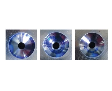
FIG 1 Various nozzle tips blued off against a sprue bushing.
Some molders have experienced this common radius mismatch problem. To overcome it, they use a ¾-in. radius on the sprue bushing and mate it with a ½-in. radius on the machine nozzle tip. That’s way too aggressive, and a bit dangerous for my liking. As shown seen in Fig. 2, all of the carriage pressure is applied to the sharp edge of the sprue-bushing orifice, which can cause it to hob or roll over. That can create several other molding problems.
A more precise method to correct a radius mismatch is to either grind the machine nozzle tip to a 0.496-in. spherical radius, or EDM the sprue-bushing nozzle seat to a 0.505-in. radius. EDM-ing the sprue-bushing nozzle seat is the preferred method because the EDM, or stipple finish, improves the shutoff between the two components. However, the same result can be obtained with a light sand blast of the machine nozzle tip.
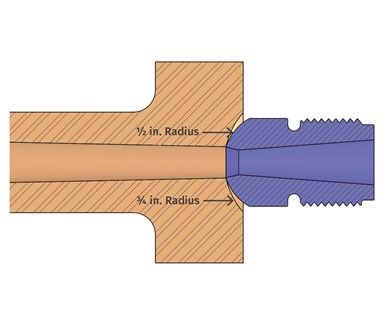
FIG 2 A 3/4-in. sprue bushing and a 1/2-in. nozzle tip.
Whichever method you choose, having a rough finish will give you another benefit. Bring the carriage forward until the two components meet. Then retract the carriage and inspect the textured surface. The rough finish gives you an excellent visual indicator of the alignment or misalignment of the carriage to the mold when under pressure, as shown in Fig. 3.
A rough surface finish improves the nozzle shut-off.
The rule of thumb in our industry is to use a machine nozzle tip orifice 1/32- in. smaller than the sprue bushing orifice to prevent any sticking of the sprue in a cold-runner mold. That’s fine for most cold-runner molds, but it’s terrible for hot-runner molds. For hot-runner molds, the orifice size should be no more than 0.010 to 0.015 in. smaller than the orifice of the sprue bushing. All it takes is a drill bit and a reamer to fix this problem. The drill bit gives you the preferred diameter. The reamer is used from the back of the nozzle tip, to reduce the straight land length, which ideally is no more than one-third the orifice diameter. When reaming the tip, just be careful not to enlarge the critical ½- in. opening in the back, where it seats against the nozzle body.
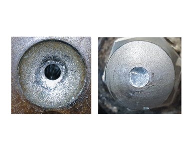
FIG 3 Rough surface finishes on a nozzle tip and sprue bushing.
Engrave the modified tip with the mold number. Buy a 7/8-in.-14 nut and tack weld it to the top of the mold. At the end of the production run, remove the nozzle tip from the barrel and screw it into the nut. Now the perfectly sized tip will stay with the mold for the next production run. Nozzle tips are cheap. Why we don’t assign a particular tip to every mold is beyond me. If you want the same results run after run, you have to use the exact same type and size nozzle tip.
Assign a particular nozzle tip to every mold.
I weigh about 200 lb and have a 9½ in. shoe size. If I asked you to lay face down on the ground, and I stood on your back, you would probably have some choice words to say to me. If a petite woman, who weighs half as much as I do soaking wet, got on your back, it might actually relieve some of your back pain. Now if she stood on one foot wearing a ¼-in.-square high heel, despite her much lighter weight, you are going to go to the hospital. Why? Because P = F/A or Pressure = Force/Area.
An easy way to remember this mathematical formula is PSI = P/SI, which obviously stands for pounds per square inch, equals pounds divided by square inches. Simple enough. Now let’s do the math: The woman’s weight of 100 lb / (¼ × ¼ in. heel size) = a whopping 1600 psi.
So what does this have to do with material leaking? Most molding machines use either a hydraulic cylinder or a spring pack (a stack of Bellville washers) to push the injection carriage up against the sprue bushing. This is called the nozzle touch force. Kudos to those of you who know what the nozzle touch force is on your various machines.
But what really upsets me is that machine manufactures seem to use a nozzle touch force relative to the weight of the machine’s injection carriage. They should use a nozzle touch force relative to the machine’s maximum injection pressure. Smaller machines typically have higher injection-pressure capabilities, yet they have some of the lowest nozzle touch forces—especially on electric machines. If there is not enough nozzle touch force to resist the injection pressure of the material, it will cause the machine carriage to blow back, which causes material leakage and creates that hog’s head we all know and don’t love.
If your shot size is too large, or if a gate gets blocked or freezes off due to a contaminant or failed heater, the screw is still going to do everything it can to keep going until it reaches the transfer position. When it hits that brick wall prior to the transfer position, the peak pressure will spike—often exceeding the forces trying to prevent bad things from happening. While you don’t want to have a pressure-limited process, you also don’t want to max out the available injection pressure. It will only make the probability of a leak that much more likely. The extra material will either compress or find someplace else to go. It can flash the parting line, leak out of any of the hot-runner shut-off surfaces, or push the carriage back and ooze out of the sprue bushing.
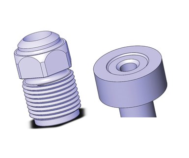
FIG 4 A relieved nozzle tip and sprue bushing.
There’s not much you can do about flashing the parting line, or leaking in the manifold, but you can easily reduce the odds of the material pushing the carriage back. The machine’s nozzle touch force is typically a fixed number. You can’t increase it or decrease it. But you can reduce the amount of contact area between the machine nozzle tip and the sprue bushing. As in the previous example, reducing the contact area increases the holding pressure. It’s the same premise as relieving a mold’s parting line to increase clamp pressure and thereby prevent flash.
Reducing the contact area increases the holding pressure.
If any of your molds have a sprue orifice (hot or cold) less than or equal to ½ in., there is no need to use a ¾-in. radius on either the sprue bushing or the nozzle tip. Contrary to what you might think, it will actually increase the chance of material leaking out. If you are using one of those oversized “mushroom” tips, you are really looking for trouble.
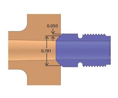
FIG 5 Nozzle tip overhang.
There are two equally effective ways to reduce the amount of contact area between the nozzle tip and the sprue bushing. You can either reduce the outside diameter of a small section of the nozzle tip, or decrease the 3/16--in. (0.1875 in.) depth of the sprue bushing nozzle seat, as shown in Fig. 4. I prefer to reduce the nozzle-tip diameter, assuming the nozzle tip will be staying with the mold. If you reduce the depth of the sprue bushing, it will only increase again if the nozzle seat is ever re-faced.
The hex flats on a typical machine nozzle tip are 7/8 in. (0.875 in.) apart. The chord length, which is the largest diameter of the nozzle seat on the end of a sprue bushing with a ½-in. radius is 0.781 in. wide. Therefore, a standard nozzle tip is already extending beyond the nozzle seat by about 0.050 in. per side, as seen in Fig. 5. If you have a problem with blowback, reduce the diameter of the nozzle tip below this 0.781-in. diam.
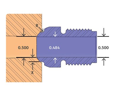
FIG 6 Relieved nozzle tip for 1/2-in. flow channel.
Let’s say your hot-runner sprue bushing has a ½-in. diam. orifice and you have issues with blowback. The standard size of the opening on the back of a machine nozzle tip is also ½ in. Drill out a general-purpose nozzle tip to 31/64 in. (0.484 in.), and stone the bore to “break” the small step you just created inside. Be careful not to increase the ½-in. opening in the back of the nozzle tip. Now relieve the outside diameter of the front of the nozzle tip, which will decrease the contact area and increase the resulting nozzle touch force, as shown in Fig. 6. How much you decrease the diameter below the 0.781-in. chord length is a compromise between how much more force you need to overcome the blowback and how weak are you safely willing to make the remaining wall section, shown as “X.” Just remember to add a radius, R, at the transition, so as not to create a stress riser on the inside corner.
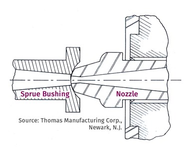
FIG 7 A 1947 nozzle tip.
If you think the suggestions I have made in this article are relatively new or novel, look at Fig. 7. That is a drawing of a machine nozzle tip used in 1947. It has a smaller spherical radius and a relieved outer diameter, to prevent blowback and hog’s heads. It is over seven decades old and yet it is a better design than every type of nozzle tip available to molders today. Let’s stop learning from our mistakes, and start learning from those who have already solved them.
About the Author: Jim Fattori is a third-generation injection molder with more than 40 years of molding experience. He is the founder of Injection Mold Consulting LLC, and is also a project engineer for a large, multi-plant molder in New Jersey. Contact: jim@injectionmoldconsulting.com; injectionmoldconsulting.com


Related Content

The Strain Rate Effect
The rate of loading for a plastic material is a key component of how we perceive its performance.
Read More
How to Get Rid of Bubbles in Injection Molding
First find out if they are the result of trapped gas or a vacuum void. Then follow these steps to get rid of them.
Read More
Understanding Strain-Rate Sensitivity In Polymers
Material behavior is fundamentally determined by the equivalence of time and temperature. But that principle tends to be lost on processors and designers. Here’s some guidance.
Read More
How to Stop Flash
Flashing of a part can occur for several reasons—from variations in the process or material to tooling trouble.
Read MoreRead Next

Lead the Conversation, Change the Conversation
Coverage of single-use plastics can be both misleading and demoralizing. Here are 10 tips for changing the perception of the plastics industry at your company and in your community.
Read More
Why (and What) You Need to Dry
Other than polyolefins, almost every other polymer exhibits some level of polarity and therefore can absorb a certain amount of moisture from the atmosphere. Here’s a look at some of these materials, and what needs to be done to dry them.
Read More
Understanding Melting in Single-Screw Extruders
You can better visualize the melting process by “flipping” the observation point so that the barrel appears to be turning clockwise around a stationary screw.
Read More