
Why Shoulder Bolts Are Too Important to Ignore (Part 2)
Follow these tips and tricks for a better design.


Let’s start off by clarifying two frequently misused names given to shoulder bolts. If the function of a shoulder bolt is to limit the distance a plate or any mold component travels, it is referred to as a range bolt. In addition to limiting travel, range bolts also serve as a safety feature. They ensure a floating plate won’t slide off its guide pins or leader pins during mold assembly, disassembly, or maintenance within the molding machine. Range bolts are almost always used in three-plate molds to control the distance that the “X” or “X-1” plate travels when stripping the runner off the sucker pins. They are also used in stripper-plate molds for the same purpose—to limit the distance the stripper plate travels when ejecting a part. Figure 1 depicts a typical installation of a range bolt.
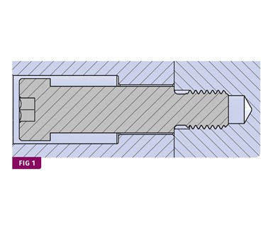
FIG 1 Typical range bolt.
If the function of a shoulder bolt is to pull a plate or any mold component, then it is called either a stripper bolt, or a puller bolt. Since there is an exception to every rule, sometimes a shoulder bolt has a dual function, where it can be both a range bolt and a stripper bolt. A common example of this is in three-plate molds, where a shoulder bolt is located between the X-1 plate and the B, or B-Retainer plate. The bolt first limits the distance between these two plates so that there is enough, but not too much, opening for the cold runner to fall freely out of the mold. As the mold continues to open, the bolt, which has now “bottomed out” in its counterbore, pulls the X-1 plate to strip the runner off the sucker pins.


Shoulder bolts in three-plate molds often take a beating out on the production floor. This is due to an inherent design flaw in standard extended nozzle bushings. The bushings create a solidified cold sprue between 0.390 in. and 0.453-in. long. These small sprues have a nasty habit of hanging up on the ID of the mating runner stripper-plate bushing when the mold fully opens. For this reason, processors intentionally open the mold quickly, so that the “X1” plate slaps against the heads of the range bolts. When the “X1” plate suddenly stops, the runner will then dislodge from the runner stripper plate bushing under its own momentum.
Occasionally, this same plate-slapping technique is used with stripper plates—typically with machines having hydraulic ejection. To avoid premature failure of the range bolts, add thermoplastic washers under their heads. The washer will absorb some of the impact and still allow the fast mold opening or stripper-plate ejection to be effective in removing the part or runner. These plastic washers—or bumpers, as I like to call them—are also terrific at reducing the deafening sound of metal striking metal, as well as preventing a plate from becoming hobbed by the heads of the bolts.
I have seen a few molds where springs were used instead of thermoplastic bumpers. That is usually not a good idea. Springs break when they are overly compressed. However, it can be useful in certain situations, such as when it’s advantageous to have a stripper plate or core insert return to its retracted position prior to the mold closing, or to allow for multiple ejection strokes.
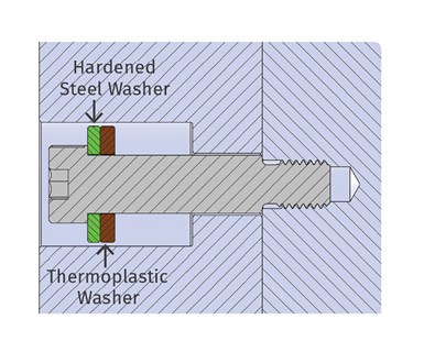
FIG 2 Shoulder Bolt with Impact Washer Assembly.
Thermoplastic washers can be made out of many different types of material. Urethane seems to be the industry standard. It’s available in various hardnesses, ranging from 40 to 95 Shore A. The higher the number, the harder the material. A Shore hardness of 90 is commonly used for range bolts, as well as elastomeric springs. Urethane is rated for use at up to 150 to 200 F, which is fine, in most cases. If you are running hot oil through a mold, you might consider using a different material, such as PC or nylon. Keep in mind, the harder the material, the lower the impact absorption. There are no hard-and-fast rules as to how thick the bumpers should be. It really comes down to the hardness of the material and the amount of force you expect they will be subjected to. For hard materials, such as PC or nylon, 0.20 in. is usually sufficient, whereas softer urethanes should be at least 0.30 in. thick. I like to use thinner bumpers, but stack two or three of them together. That way, if one fails, the bolts are still somewhat protected.
To be effective, thermoplastic washers need to be supported—typically by a flat steel washer— as shown in Fig. 2. Let’s talk about washers for a minute, so that you know which type is best for this application. The most common types of flat washers commercially available today are USS (United States Standard); SAE (Society of Automotive Engineers) Type A, in thicknesses of N for narrow and W for wide; ASME (American Society of Mechanical Engineers) Type B, in thicknesses of N for Narrow, W for wide and R for regular; Mill-Spec (Military Specification); and General Purpose.
Despite this wide selection, none of them are available in ideal sizes for this application. But don’t despair. You won’t have to make a custom washer. Some industrial suppliers offer exactly what’s needed: black-oxide-coated, case-hardened, flat steel washers, with a tight ID, an ample OD and a generous thickness. Granted, these washers will cost you $1 to $2 each, but this is not somewhere you want to cut corners.
Even though range bolts are easy to remove on the bench, there are occasions where you want to remove them in the press in order to gain access to something within the mold, or simply to remove just the floating plate. Unfortunately, there is often not enough room to install an Allen wrench in the head. Adding wrench flats or spanner-wrench pin holes to either the shoulder or the head of the bolt, will solve this problem.
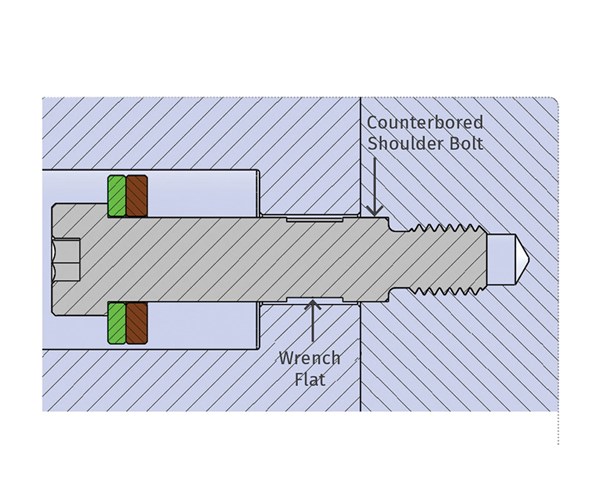
FIG 3 Counterbored Shoulder Bolt.
Side Loading
Range bolts are not designed to have a side load applied to them … but they often do. Since the thread neck under the shoulder is much smaller in diameter than the rest of the bolt, if a side load is applied it will not take a lot of force for it to fail at that location. The most common side load occurs when the bushings or leader pins that support the floating plate start to wear.
That wear, along with the original clearance, allows the plate to sag or tilt. If there is insufficient through-hole clearance and the range bolts are fairly long, the entire weight of the floating plate can rest on the range bolts when the mold is in the open position. There is a simple method for minimizing a side-load issue—counterbore the shoulder in the mounting plate to a depth of one-quarter to one-third of the shoulder diameter, as shown in Fig. 3.
There is another cause for lateral loads on shoulder bolts—thermal expansion. Ideally, all the mold plates should be at the same temperature, but processing issues often arise and the temperature of some of the plates are intentionally changed to resolve them. This is not an issue on small molds, but large molds can be problematic. In large molds, counterboring the shoulder and increasing the though-hole clearance are the best options.
Design Clearance
How much clearance should there be around the shoulder? Ideally, you want the through-hole to be as small as possible to provide the maximum amount of bearing surface. Since the concentricity and parallelism between the shoulder and the thread of a standard shoulder bolt can be out by as much as 0.005 in./in., the amount of clearance should be based on the length of the bolt. Additional clearance should be added to account for any angularity of the tapped hole the bolt screws into: 1/32 in. for shoulder lengths up to 4 in. and 1/16 in. for shoulder lengths up to 8 in. is usually sufficient.
Not only should range bolts be located symmetrically about the centerline of the mold, they should be in close proximity to the component that is pulling or pushing the floating plate. For example, if you use ejector return pins to advance and retract a stripper plate, locate the range bolts alongside them. If the range bolts are too far away, the floating plate might bend permanently. It should go without saying that the location of the range bolts should also take into consideration the need for manual, automatic or robotic part removal, as well as accessibility to the parting line during start-up.
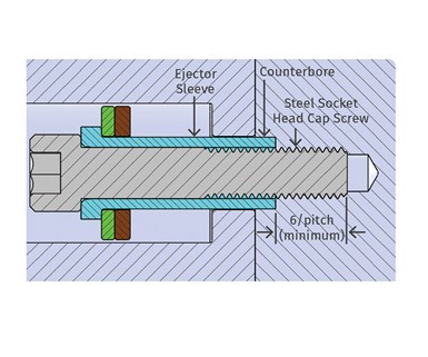
FIG 4 Custom Shoulder Bolt.
In last month’s article, I discussed how shoulder bolts often come loose because they have a very short effective length—the distance between the last thread and the underside of the shoulder. The effective length controls the amount a bolt will stretch. A stretched bolt is in tension and resists unthreading due to vibration and impact. If a range bolt unscrews during a production run, serious damage to the mold can occur. The best way to prevent this from happening is to make a custom range bolt using a standard alloy-steel socket-head cap screw and a standard ejector sleeve, as shown in Fig. 4. This design is especially helpful for very long-range bolts, where standard lengths are not available.
Many of you are probably thinking that making a custom-sleeved range bolt is overkill, and that some thread-locking compound will solve the problem. That’s usually not true. There are several reasons the sleeved design is more advantageous. Many thread-locking compounds are fairly viscous. A shoulder bolt’s Class 3 thread has almost no clearance with the tapped hole, so you won’t have enough compound to be effective. Less-viscous compounds work a little better, but now you might have to use a torch to loosen the bolts. Additionally, standard shoulder bolts don’t often come in the exact length you want, so you are forced to use ones that are longer than you need. That can create an issue with the molding machines daylight, which is the maximum distance between the platens. Standard shoulder bolts often break when someone changes the mold opening speed or has an incorrect mold open position setpoint—especially on hydraulic machines that can’t stop on a dime. A standard shoulder bolt can’t handle the load because it has such a small effective length. The sleeved bolt design is much more forgiving in these situations.
The last thing I want to mention is that if the shoulder bolt or ejector sleeve is large enough, and the counterbore is deep enough, you can install a bushing on the shoulder to support the floating plate. This eliminates the need for additional guide pins and bushings. It can allow the mold base to be smaller or simply free up some room for other components. While I don’t recommend this type of design, there are times when a mold needs to fit in the smallest machine possible, or the smallest machine available. Since the hourly rate of a molding machine is typically based on the machine size or tonnage, space-saving designs can help lower the cost of the part.
About the Author
Jim Fattori is a third-generation injection molder with more than 45 years of molding experience. He is the founder of Injection Mold Consulting LLC. Contact jim@injectionmoldconsulting.com; injectionmoldconsulting.com.


Related Content

Where and How to Vent Injection Molds: Part 3
Questioning several “rules of thumb” about venting injection molds.
Read More
How to Start a Hot-Runner Mold That Has No Tip Insulators
Here's a method to assist with efficient dark-to-light color changes on hot-runner systems that are hot-tipped.
Read More
Optimizing Pack & Hold Times for Hot-Runner & Valve-Gated Molds
Using scientific procedures will help you put an end to all that time-consuming trial and error. Part 1 of 2.
Read More
Improve The Cooling Performance Of Your Molds
Need to figure out your mold-cooling energy requirements for the various polymers you run? What about sizing cooling circuits so they provide adequate cooling capacity? Learn the tricks of the trade here.
Read MoreRead Next

Troubleshooting Screw and Barrel Wear in Extrusion
Extruder screws and barrels will wear over time. If you are seeing a reduction in specific rate and higher discharge temperatures, wear is the likely culprit.
Read More
Lead the Conversation, Change the Conversation
Coverage of single-use plastics can be both misleading and demoralizing. Here are 10 tips for changing the perception of the plastics industry at your company and in your community.
Read More
People 4.0 – How to Get Buy-In from Your Staff for Industry 4.0 Systems
Implementing a production monitoring system as the foundation of a ‘smart factory’ is about integrating people with new technology as much as it is about integrating machines and computers. Here are tips from a company that has gone through the process.
Read More