
Residence Time and Residence-Time Distribution—Part 1 of 2
Failing to calculate and accurately account for residence time can compromise material integrity before it’s even injected.


Most thermoplastics are organic materials, and their chemistry is such that they are not able to withstand melt-processing temperatures beyond a certain time. Data from studies with Valox 420, a commonly available PBT from SABIC, show that when it is subjected to a temperature of 500 F for 6 min, the molecules will have broken down and the properties of the plastic are lost (Fig. 1).
The property studied here is viscosity. We conclude that the maximum residence time for this PBT at 500 F is 6 min. However, I’d consider this to be too broad a definition of the maximum residence time for a given material, since there is no mention anywhere of any absolute or percentage drop in any specific property. An over-designed part, or a part that is not subjected to a load, could probably function even if it is molded with some number of molecules that are degraded and have a lower molecular weight. There are also additives that can degrade base resins, adding another layer of complexity.


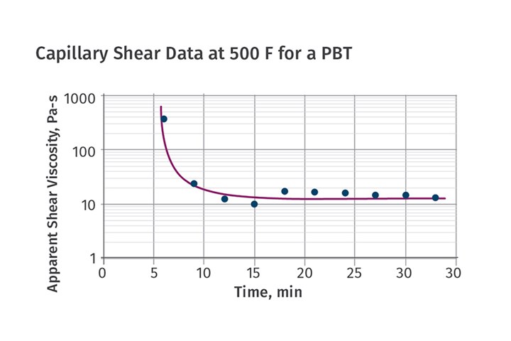
FIG 1 Studies with SABIC’s Valox 420 PBT show that the molecules break down and viscosity properties of the material are lost when it is subjected to a temperature of 500 F for 6 min.
Calculating Residence Time
Residence time is the time that the plastic spends in the molding barrel. To be precise, it is the time from when the plastic pellet is at the bottom of the hopper and on the screw ready to be conveyed until the time it reaches the tip of the nozzle. It can be calculated with a very simple formula, but that formula is really just an estimate. To understand this, let us first understand the calculation for the maximum amount of plastic inside the barrel. Many molders would just use the published value of the maximum shot capacity of the machine. This is acceptable, but not entirely accurate.
To keep things simple, let’s say the parts we’re concerned with are molded in PS, the standard material that machine shot capacity is specified in. Consider the maximum shot capacity of this machine to be 100 g. Shot weight is defined as the total weight of the parts and runners. For the discussion below, let us also ignore the small amount of cushion that must be present at the end of the compensation—pack and hold—phase.
Scenario 1: Maximum Shot Capacity
This should never be the case, but let’s say the shot weight is 100 g; in other words, 100% of the maximum shot capacity is being used to mold the parts. If the screw is retracted all the way back to its maximum-shot-size position, then there are 100 g of plastic in front of the screw tip (Fig. 2). In addition to this material, there is plastic on the screw. All the plastic in the metering section of the screw is molten; the plastic in the compression section is partially molten; and the plastic in the feed section is in the process of softening and will be melted soon.
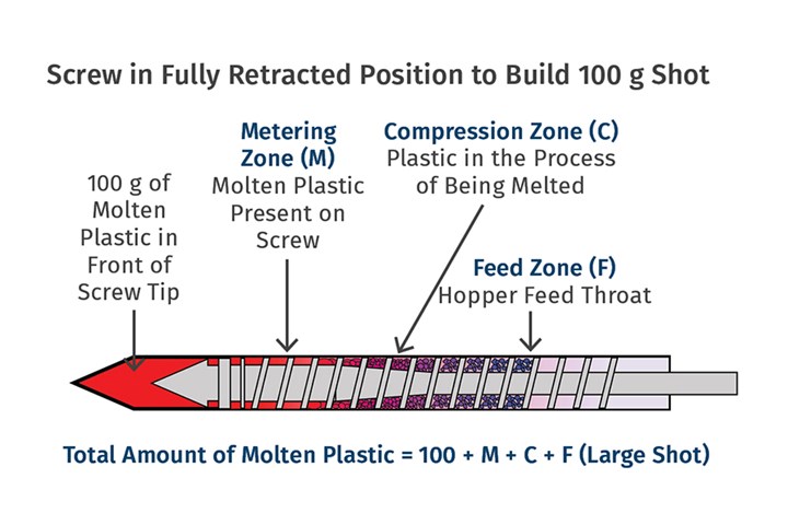
FIG 2 Here, if the shot weight is 100 g, 100% of the maximum shot capacity is being used to mold the parts. If the screw is retracted all the way back to its maximum-shot position, then there are 100 g of plastic in front of the screw tip.
In such a situation, the maximum amount of molten plastic is more than 100 g. It is clear here that screw-design factors—L/D ratio, compression ratio, ratio of the length of the feed section to compression to metering, and the screw type—will play a role in determining the amount of molten plastic on the screw.
Scenario 2: Minimal Shot Capacity Used
For our next example, let’s say the shot weight is 20 g, meaning 20% of the maximum shot capacity is being used. Similar to the discussion in Scenario 1, the total amount of molten plastic in the barrel will be 20 g in addition to the molten plastic on the screw.
Assuming that all processing parameters other than the shot size are identical in both scenarios, you can see that the amount of plastic in the metering section and in the compression section of the screw is identical (Fig. 3). However, the amount of plastic in the feed section will be higher in the second scenario, where 20% of the shot size is used compared to the 100%.
It is clear that estimating the amount of plastic inside the barrel is a function of several factors. Not mentioned so far is the effect of processing parameters, especially backpressure. To truly calculate the maximum amount of molten plastic in the barrel, a molder must add the amount of plastic in front of the screw to the amount of molten plastic on the screw in each of the sections.
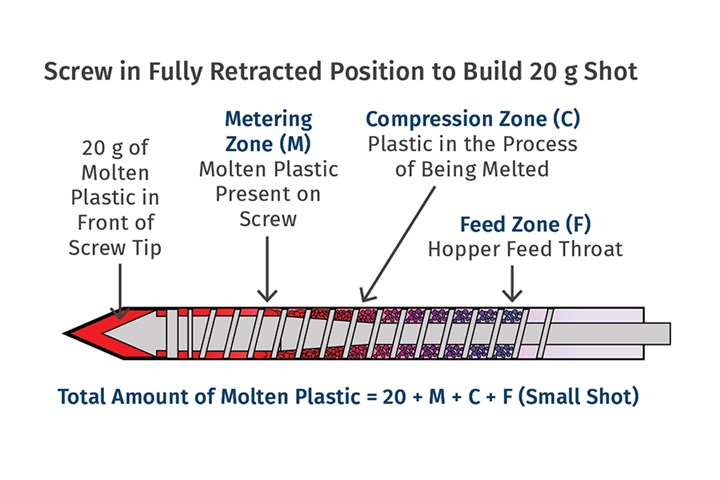
FIG 3 Here, assuming that all processing parameters other than shot size are identical to the Fig. 1 scenario, you can see that the amount of plastic in the metering section and in the compression section of the screw is identical. However, the amount of plastic in the feed section will be higher here, where 20% of the shot size is used, vs. 100% used in Fig 2.
In a case where the percentage usage of the maximum shot size is high—say 70% of the maximum—the resin may be subjected to the processing melting temperatures even in the feed zone. The amount of plastic that we talk about here is the melt-processable plastic, and it is difficult to estimate where on the screw the plastic has reached the melt-processable temperature. Surely, screw-design information from the manufacturer can provide insights about the volume of the plastic in each of the sections, and this can be used for calculations.
Estimating the amount of plastic inside the barrel is a function of several factors.
How Many Shots in the Barrel?
Once we know the amount of plastic in the barrel, we can divide this number by the shot weight and that will be equal to the number of shots in the barrel. Multiplying the number of shots by the cycle time will give the total time the plastic spends in the barrel.
For example, if the amount of the plastic on the screw and a built-up shot is 150 g and the shot weight is 25 g, then we can calculate that the number of shots in the barrel is six. If the cycle time for these parts is 30 sec, then we multiple that cycle time by the number of shots to determine it will take 180 sec (3 min) for the plastic to be conveyed from the location where it melts to the nozzle tip. Again, this does not include the material that has not yet reached the melt temperature, and so some portion of the plastic in the feed zone is not considered.
Clearly, this is not easy or practical to perform in a day-to-day operation. To keep things simpler, there is a widely used formula to calculate the number of shots in the barrel:
Number of Shots = Maximum Machine Shot Capacity ÷ Shot Weight
Here also, residence time is calculated by multiplying the number of shots in the barrel by the cycle time. This formula works well for the most part but as we now know is not 100% accurate.
Practical Method of Determining Residence Time
There is a very easy and practical method to determine the number of shots in the barrel, however, it does not work well on dark-colored parts. In such cases, if possible, running the same mold with a lighter color or natural material will help. In this method, start molding the parts, move the hopper away from the feed throat and, using a mirror or a phone camera, observe the plastic being fed onto the screw. Please observe safety and never look directly into the hopper.
As soon as you see the bare screw, drop one or two pellets of any dark compatible color into the feed throat and pull the material hopper back in place. Let the mold open and eject the shot. Now start counting the number of shots until you see the color show up on the parts.
If the color showed up on the eighth shot, then there are at least seven shots in the barrel. The eighth shot has some color. To be on the safe side, you could say there are eight shots in the barrel. Multiply eight by the cycle time to get the residence time of the plastic in the barrel. As an example, if the cycle time is 40 sec then the residence time would be 8 × 40 = 320 sec or 5.4 min. If the maximum residence time for this plastic is say 6 min, then the parts do not have any degraded plastic. However, if the maximum residence time for this material is 4 min, then degradation is a definite concern.
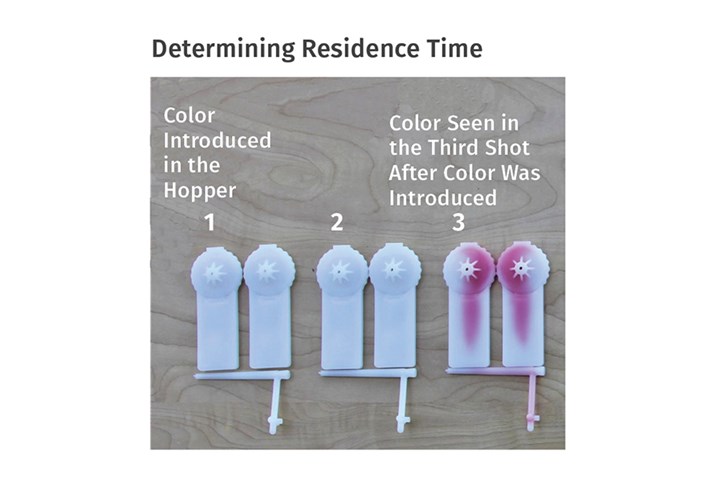
FIG 4 To help determine the number of shots in the barrel, start molding parts; move the hopper away from the feedthroat and use a mirror or a phone camera to observe the plastic being fed onto the screw. When you see the bare screw, drop one or two pellets of any dark compatible color into the feed throat and pull the material hopper back in place. Let the mold open and eject the shot. Now start counting the number of shots (three, in this case) until you see the color show up on the parts.
An example of this experiment is shown in Fig. 4, where the color showed up in the third shot. These set of parts will be used to continue this topic in Part 2 of this column, which will focus on residence-time distribution.
ABOUT THE AUTHOR: Suhas Kulkarni is president of Fimmtech Inc., which specializes in services and training related to plastic injection molding. He earned his Masters in Plastics Engineering from the University of Massachusetts, Lowell, as well as a Bachelors in Polymer Engineering from the University of Poona, India. He has 27 years’ experience as a process engineer and is the author of Robust Process Development and Scientific Molding, published by Hanser Publications, now in its second edition. He also works as a contract faculty member at U.Mass.-Lowell. Contact: suhas@fimmtech.com; fimmtech.com.


Related Content

How to Optimize Pack & Hold Times for Hot-Runner & Valve-Gated Molds
Applying a scientific method to what is typically a trial-and-error process. Part 2 of 2.
Read More
Know Your Options in Injection Machine Nozzles
Improvements in nozzle design in recent years overcome some of the limitations of previous filter, mixing, and shut-off nozzles.
Read More
What to Do About Weak Weld Lines
Weld or knit lines are perhaps the most common and difficult injection molding defect to eliminate.
Read More
Understanding the ‘Science’ of Color
And as with all sciences, there are fundamentals that must be considered to do color right. Here’s a helpful start.
Read MoreRead Next
Optimizing Pack & Hold Times for Hot-Runner & Valve-Gated Molds
Using scientific procedures will help you put an end to all that time-consuming trial and error. Part 1 of 2.
Read More
Determining Vent Depths in Injection Molding
Experiments reveal the relationship between vent depths and part thickness, allowing molders and moldmakers to more precisely determine vent dimensions.
Read More
Process Capability and the ‘Hesitation Effect’
Understanding the concepts of pack and hold and applying them during process development is critical for molders to achieve consistent part quality.
Read More