
Simulation Meets Reality: Physical & Virtual Molding of LSR
Growing sophistication in simulating the molding performance of LSR is evident in the case of this exceedingly complex part. Actual molding trials validated the predictions of simulated ‘virtual molding.’
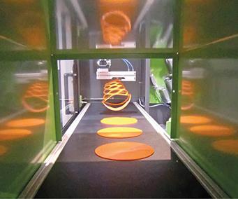
Demolding Ursula at the Fakuma 2015 show. (Photo: Momentive Performance Materials)
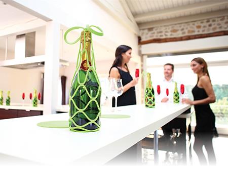
Ursula, the bottle carrier mesh named after the Bond girl. (Photo: CVA Silicone)
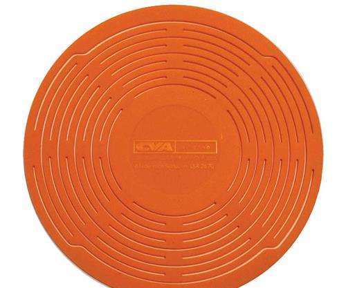
Ursula in its as-molded state.

Crosslinking curves of Silopren LSR 2670, measured at three different temperatures with a moving-die rheometer. Data such as this, not usually found on data sheets, is necessary for accurate LSR molding simulation.
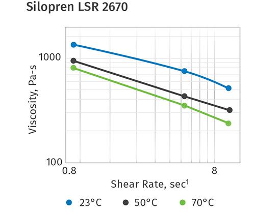
Viscosity curves of Silopren LSR 2670 at three different temperatures and shear rates (made with a cone-and-plate rheometer) are another example of the data required for LSR simulation.
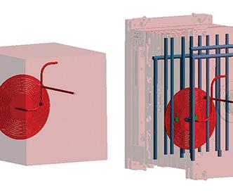
Simulation setup under the classical (left) and virtual molding approach (right).
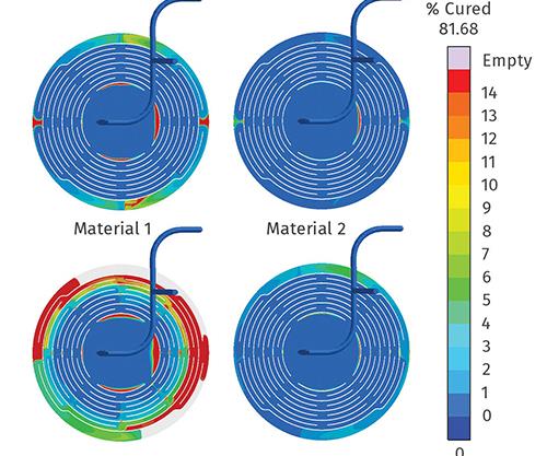
A mold-filling evaluation shows little difference between Silopren LSR 2670 (right) and a similar LSR (left) when using the classical simulation approach (top row). Significant differences between the two materials becomes apparent when using the more complete virtual molding approach (bottom row).
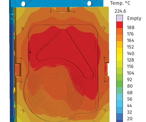
The moveable mold half shows temperature differences of more than 30° C even after reaching the thermal steady state, which required more than 25 cycles. Classical simulation only looks at a single cycle and so cannot capture the changes in mold temperature after startup.
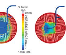
Virtual molding prediction of curing degree at 25.5, 29.5, and 35.5 sec (left to right) of the curing phase.
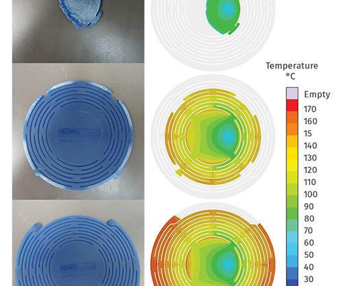
Comparison of actual short shots shows good agreement with virtual-molding simulation at 10, 40 and 60 cm³ of fill (top to bottom).


Since its market introduction in 1979, LSR (liquid silicone rubber) continues to grow faster than the overall plastics market. An important driving force for this success is its outstanding performance in modern injection molding processes. Most commercial LSR injection molded articles are processed in a fully automated, trim-free, and wasteless setup using cold-runner molds. Consequently, LSR technology requires a higher investment in the mold and equipment than conventional elastomer parts.
In the special environment of LSR materials, processing simulation can provide high value. There are significant costs associated with physical mold trials, and rework on such precision molds is tedious and time consuming. Shifting these efforts from the production machine into the “virtual” simulation environment reduces the risk and cost of building a precision mold and finding the most efficient process with respect to quality and cycle time.


LSR has a unique flow and viscosity profile in combination with special curing characteristics. The heat-activated crosslinking reaction is chemically inhibited (as part of the LSR formulation) and starts only at temperatures exceeding 230 F (110 C). This makes it difficult to guess the limits of cavity design and process parameters just by experience. Current simulation tools like Sigmasoft Virtual Molding allow a deeper understanding of the filling and crosslinking behavior of particular designs by combining the entire mold and cold-runner system, including the individual water channels or electric cartridge heaters, with the desired molding process, cycle by cycle.
A recent example highlighting the potential of LSR molding of complex shapes is the designer product “Ursula” (named for the first James Bond girl, Ursula Andress) produced by molder CVA Silicone in France. The part is a protective carrier for bottles, which received an award at the Biennale du Design Français. Its flow length of up to 619 mm (more than 24 in.) with a thin wall of just 3 mm (~0.1 in.) and a shot weight of 73 g (~2.5 oz) combines different challenges for elastomer molding, which can only be managed by a robust process and tool design, along with a highly processable LSR material.
Results obtained with the single-cavity cold-runner mold from CVA Silicone were presented during last fall’s Fakuma 2015 show in Friedrichshafen, Germany. The parts were molded with Momentive Silopren LSR 2670 liquid silicone rubber on an Engel e-mac 100 machine with integrated robotic handling in a cycle time of approximately 1 min. In the next hall of the same tradeshow, Sigmasoft demonstrated virtual molding of the part, utilizing the same processing conditions.
This kind of virtual molding simulation requires detailed material data. This applies not just to the LSR material, but also to the different metals of the mold (plates, cavity, ejectors, etc.) and cold-runner deck, as well as to the cooling media. Most of those values can be taken from literature or are already built into the simulation software.
In case of LSR and other elastomers, the polymer material properties available in datasheets (typically tensile strength, elongation at break, tear resistance, density, etc.) are insufficient to perform the necessary mathematical operations for accurate molding simulation. Material data for the molding simulation of LSR include crosslinking as a function of time, and viscosity as a function of shear rate, at different temperatures. Other necessary material data include thermal conductivity, heat capacity, CTE, and Poisson’s ratio.
Crosslinking was measured on a moving-die rheometer at three different temperatures (110, 130, and 150 C). Here the LSR (mixed parts A and B at a ratio 1:1) is measured between two heated plates turning against each other. With the temperature increase from 110 to 150 C, the crosslink density increases more rapidly and the plateau is reached in a shorter time (see Fig.1).
The viscosity was measured on a cone-plate viscometer at three different temperatures (23, 50, and 70 C) and three different shear rates (0.9, 5, and 10 sec-1). Here the A and B components were measured separately and the total viscosity was averaged from the 1:1 blend ratio (Fig.2).
Using material models, the software extrapolates the required values from the measured data. Above material properties were measured by Momentive for this demonstration and used in Sigmasoft for the virtual molding process.
GOING BEYOND SIMPLE SIMULATION
The crucial point of virtual molding is to achieve reliable calculations of the material behavior during filling and curing. This involves a fully coupled model incorporating the complete mold and molding process together with the material data. Such coupling ensures that the ever-changing mold temperature reliably impacts the LSR throughout the complete production cycle. A complete virtual molding analysis is possible only when all of these components are incorporated, because the real information is now replacing the previously used assumptions from the classical simulation approach.
Simplified preliminary simulation evaluations of filling and curing behavior can provide valuable insight. They require less information and are often supplemented with user-defined assumptions to bridge the gap of missing information. When should more thorough virtual molding simulation be used instead of classical simulation approaches?
The complex geometry of the Ursula product is a good example to evaluate the outcome of both approaches. This product requires a material with high stability in rheological properties and curing kinetics, as well as an elaborate cooling and cold-runner design for the mold to ensure process capability and stability.
For the classical simulation, a 3D model of the part and runner are imported and a generic mold cube is assembled around these geometries. Without considering actual mold components, the thermo-physical properties are limited to only one mold material (there are no inserts or parting lines), and the initial temperature of the mold is assumed to be constant. There cannot be any heat lost by radiation at the parting plane because there is no parting plane, and the simulated mold temperature is the result of ideal, user-defined boundary conditions (Fig. 3, left).
Without electrical-heater and parting-line information, there is also limited processing information—actual curing time, mold opening/closing times, etc. This approach is nonetheless suitable for a first estimation or general impression of the filling behavior, even though it cannot deliver reliable results for the final mold and process. In actuality, the temperature distribution within the mold and throughout the production cycle is constantly changing and, for accurate calculations, cannot be assumed as a homogeneous user-defined input. Especially for complex materials and processes like this one, this factor cannot be neglected.
The virtual molding approach includes all of the mold plates, cavities, electrical heaters, cold deck, water channels, etc.—all defined as actual 3D components. There are no limitations as to the description of multiple mold materials or their operational times (when they are or are not in contact with each other or the part), how heat flows through one mold half while the mold is open, etc. (Fig. 3, right).
After the heating-up of the mold, multiple consecutive production cycles are simulated and a true thermal gradient within the mold is established, replacing the previously mentioned assumptions.
During the customer trials, two similar LSR materials were designated for the production of the Ursula part. After some trials, Momentive Silopren LSR 2670 was identified as the best material for the process. Both materials were evaluated using the classical as well as the virtual molding simulation approaches, revealing why only one material was up to the task.
In the first evaluation under the classical simulation approach with a homogenous mold temperature of 356 F (180 C), it seemed like both materials could be used (Fig. 4, top). However, the virtual molding approach showed this was not the case. One of the materials could not completely fill the cavity due to premature curing (Fig. 4, bottom left). This difference resulted from the materials’ different curing characteristics combined with the high temperature difference within the cavity during filling. That actual thermal gradient was not available in the single-cycle simulation because it required multiple (>25) production cycles before it was evident.
The reason behind the different outcomes was the temperature distribution inside the mold. While the classical approach assumed a homogenous temperature, the virtual mold showed large temperature variations. After the thermal steady state was reached, inspection of the movable half revealed that just inside the cavity, there was a temperature difference greater than 50° F/30° C (Fig. 5). Exposed to the hot areas at the top of the cavity, one of the two LSR materials quickly reached a curing degree of over 20% at the flow front, even though the “alpha gel” point of no-flow was at only 10% cure. On the other hand, the Silopren LSR 2670 proved more stable, and while the curing degree also rose, it did not impair the filling behavior. As in reality, it still ensures a good part quality (Fig. 4, bottom right) despite the inhomogeneous mold temperatures.
The temperature distribution inside the cavity influenced not only filling but also the curing behavior of the Ursula part. Further evaluation of the process using the Silopren LSR 2670 showed that the curing reaction began at the top of the cavity (Fig. 6, left) and then moved from the outside to the center of the part (Fig. 6, middle and right). Possible counter-measures to obtain smoother curing behavior and more balanced filling include adjustments to the power settings or a different location of the heating cartridges. Both options could safely be evaluated in the virtual molding model prior to making changes in the real mold.
After the virtual molding analysis was completed, the congruence of the calculated results and reality was verified. For this purpose, short shots (partial fillings) were compared with the simulated results during filling. With the part volume of 72 cm³, a short shot was prepared at every 10 cm³ of fill. These short shots were compared with the corresponding simulation results at points where the same amount of material was inside the cavity.
Figure 7 shows the comparison for the short shots of 10, 40, and 60 cm³. The slightly asymmetric filling pattern is a direct result of the offset gate position. There is a remarkable correlation between the virtual molding results and actual production shots, as is clearly identifiable from Fig. 7. The locations where the melt is advancing more rapidly are evident, making the results and partial fillings easy to compare.
This validation provides just one example where the virtual molding approach goes well beyond the capabilities of classical simulation. It provides LSR molders not only a reliable outcome but also clear background information on the specific issue and its consequences. Such information is paramount for finding a resolution efficiently.
For complex parts and processes, it is critical that a suitable material is selected. For proper selection, a deeper understanding of the actual mold construction and production conditions must be available to understand effectively why one material is not working and what specific attributes are necessary to select an appropriate one. With the input of measured material properties and process data, virtual molding helps to find the ideal setup without wasting resources on the machine.


Related Content

50 Years of Headlines … Almost
I was lucky to get an early look at many of the past half-century’s exciting developments in plastics. Here’s a selection.
Read More
How to Achieve Simulation Success, Part 2: Material Characterization
Depending on whether or not your chosen material is in the simulation database — and sometimes even if it is — analysts will have some important choices to make and factors to be aware of. Learn them here.
Read More
Take Time to Save Time: Five Steps in Mold Design to Reduce Back-End Troubleshooting
Westminster Tool shares how the one week it typically takes to perform these five steps in the design phase can save three weeks or more in an overall tool build.
Read More
Injection Molding Simulation Meets the Real World
Direct data interface between molding simulation and the injection machine links the computer model to the real-world process. This can improve results from product and mold design through ongoing production. A case study demonstrates these benefits for automotive components in a family mold.
Read MoreRead Next

Lead the Conversation, Change the Conversation
Coverage of single-use plastics can be both misleading and demoralizing. Here are 10 tips for changing the perception of the plastics industry at your company and in your community.
Read More
Troubleshooting Screw and Barrel Wear in Extrusion
Extruder screws and barrels will wear over time. If you are seeing a reduction in specific rate and higher discharge temperatures, wear is the likely culprit.
Read More
Why (and What) You Need to Dry
Other than polyolefins, almost every other polymer exhibits some level of polarity and therefore can absorb a certain amount of moisture from the atmosphere. Here’s a look at some of these materials, and what needs to be done to dry them.
Read More