
Solve Ultrasonic Horn Problems With Finite-Element Analysis
Computer modeling with 3D finite-element analysis (FEA) is used in the plastics industry because it can identify stresses, predict performance, and analyze part failures that can often be missed by traditional 2D modeling methods.


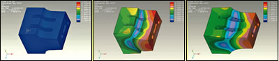
Figs. A, B, C—Isolated FEA still frames show model of failing ultrasonic horn at rest (A), compressed (B), and extended (C). “Hot” colors (red, yellow, orange) show areas of maximum vibration amplitude. Color changes indicate changes in amplitude and resulting stress.
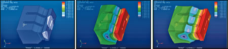
Figs. D, E, F—Isolated FEA still frames show model of optimized horn at rest (D), compressed (E), and extended (F). Reduced color variation shows more even amplitude and lower stress.
Computer modeling with 3D finite-element analysis (FEA) is used in the plastics industry because it can identify stresses, predict performance, and analyze part failures that can often be missed by traditional 2D modeling methods. In simplest terms, FEA 3D modeling creates a virtual object and breaks it up into very tiny units that can be examined and analyzed individually to yield information on the whole part.
FEA computer simulation is also proving to be a valuable tool for diagnosing stubborn ultrasonic welding problems. Specifically, FEA is being used by processors who encounter problems in achieving successful welds in assembly. FEA imagery provides a 3D computer simulation to analyze horn performance. FEA simulation predicts ultrasonic vibration frequency, amplitude, and stress. Such data can help identify a problem that was not apparent with other examination methods.


Analyzing horn performance
If you encounter weld problems or horn failures, FEA can be used to analyze horn integrity and assembly performance. For example, one manufacturer repeatedly ran into difficulties when it attempted to weld a replacement part for a refrigerator water filter. This glass-filled polycarbonate part had an aggressive shear joint that was welded at 20-kHz frequency with an automated ultrasonic press and a horn with a high-gain booster.
Problems included insufficient weld quality and frequent horn cracking. After checking and adjusting all the “usual suspects”—horn and fixture alignment, pressure levels, booster selection, and booster/horn interface—with no success, the production manager contacted us for help.
To use FEA software to analyze the failing horn and diagnose the problem, we first measured the horn and created corresponding CAD files as if we were first designing the horn. This data was entered into the FEA software along with performance parameters to create a virtual 3D replica of the horn and its action during the welding process. The computerized FEA simulation produces a digital video file that typically comprises 50 to 60 frames.
FEA simulation can be programmed to show the relative stress at various locations on the horn and a displacement simulation that shows the relative amplitude of movement at those locations. The simulations show in “live” animation the horn’s amplitude and stresses during a weld through the use of visual indicators such as color and line patterns, as well as numeric values. To a trained technician, these images provide a wealth of critical information. In the accompanying illustrations, which are still frames taken from FEA simulations, even the untrained eye can spot certain areas of higher stress and amplitude displacement.
Figure A shows the recreated model of the failing horn at rest, with no stress. As would be expected, the consistent “cool” blue color indicates very little activity (amplitude) and very little variance in that activity. Figures B and C show the horn compressed and extended, respectively, during the welding process. Looking at the lines, colors, and color patterns (minimum = blue, maximum = red) in these frames reveals significant trouble spots.
Color patterns or variances can pinpoint areas of high stress and inconsistent performance. Typically, high stress occurs in two places on a horn—in the middle (“nodal” area) and in the case of a slotted horn (like our example), at the bottom of the slots. Uneven amplitude is typically more evident at the face of a horn.
Examination of Figs. B and C reveals that there is a lot of “hot” amplitude at the face of the horn and that this amplitude is uneven across the face. There are considerable areas of different colors, all of them are in the “hot” (red-orange-yellow) spectrum. This uneven pattern signals trouble since uniform amplitude across the face of a horn is necessary to yield a uniform weld.
Additionally, the striated patterns of each color follow very uneven lines and show drastic curvature and motion. Comparing the lines of the horn surfaces during compression and extension to the lines of the horn at rest also shows a great deal of deformity and stress.
Based on the FEA animation sequence, it is even more evident that, in addition to vibration, the horn is subjected to fairly severe twisting, corkscrew-like motion that creates a great deal of internal stress in the horn that would lead to cracking and failure.
Creating a new horn
So far, FEA has helped us identify the problems with this welding horn. The real beauty of FEA is that it can now be used to solve those problems by creating and testing a new horn virtual model that performs better under the actual application parameters. Since this new, improved horn is “built” and tested on the computer, there is no waste of expensive materials like aircraft-grade titanium or aluminum, or valuable machining time. A variety of changes to the horn size, shape, and structure can be tested via simulation until the desired results are achieved. These virtual test results have proven to be very accurate predictors of real-world performance.
In the case of our failed horn, Figs. D, E, and F show the final new horn design and the corresponding FEA results. The horn has been reshaped with several major modifications, including an increase in the surface area of the face, addition of undercuts, and a change in the size and position of the slots.
An examination of the “before” and “after” drawings reveals several performance improvements. While there is still a lot of activity at the face of the horn, there is much more uniform amplitude across the face (indicated by the more consistent color distribution). The lines of the different colors and their respective patterns are much more even and proportionate, indicating less variance in activity. This produces less stress and the stress is more evenly distributed. Likewise, a review of the structural lines shows significantly less distortion and stretching in all areas.
This improved horn was physically built and has performed trouble-free with no failures in automated production. Furthermore, it now runs with a low-gain booster, creating less stress on the horn and delivering a more comfortable setup.
Manufacturers who en counter failed horns or a stubborn ultrasonic welding problem should consider 3D FEA analysis. It’s no longer “rocket science” and the software is in common use by many engineers and horn manufacturers.
Brian Gourley is technical services manager and Andy Rushton is mechanical design manager at Sonics & Materials Inc., Newtown, Conn., a maker of ultrasonic welding and other plastics assembly equipment. The authors both have over 20 years of experience in plastics welding visit Sonics & Materials, Inc.'s PT Online Showroom.


Related Content

Recycled Material Prices Show Stability Heading into 2023
After summer's steep drop, most prices leveled off in the second half.
Read More
Inside the Florida Recycler Gearing Up to Take on Scrap at NPE2024
Hundreds of tons of demonstration products will be created at NPE2024 next spring. Commercial Plastics Recycling strives to recycle all of it.
Read More
Scaling Up Sustainable Solutions for Fiber Reinforced Composite Materials
Oak Ridge National Laboratory's Sustainable Manufacturing Technologies Group helps industrial partners tackle the sustainability challenges presented by fiber-reinforced composite materials.
Read More
Purpose-Built System Enhances Capacity and Flexibility for Recycler
A Boston recycler invested in a turnkey shredding, granulation and elutriation system to expand its plastics reclaim business.
Read MoreRead Next

People 4.0 – How to Get Buy-In from Your Staff for Industry 4.0 Systems
Implementing a production monitoring system as the foundation of a ‘smart factory’ is about integrating people with new technology as much as it is about integrating machines and computers. Here are tips from a company that has gone through the process.
Read More
Processor Turns to AI to Help Keep Machines Humming
At captive processor McConkey, a new generation of artificial intelligence models, highlighted by ChatGPT, is helping it wade through the shortage of skilled labor and keep its production lines churning out good parts.
Read More
Troubleshooting Screw and Barrel Wear in Extrusion
Extruder screws and barrels will wear over time. If you are seeing a reduction in specific rate and higher discharge temperatures, wear is the likely culprit.
Read More