
Solving 10 Common Challenges In Extruding Thin-Gauge Sheet
Troubleshooting: Sheet Extrusion
Thin-gauge sheet production presents some unique challenges to the extrusion operator, including the following set of 10 commonly encountered considerations
There are three basic methods for counteracting the adverse effects of roll deflection. Of these, roll skewing is the most versatile. It employs a cross-axis positioning of the roll so that the roll deflection is wrapped about the mating roll, creating a uniform gap over a wide operating range.
A horizontally configured roll stand eliminates the adverse effects of sag and droop and permits introducing the melt bank precisely and directly into the primary roll nipping location.
Controlling the melt-bank position is essential to avoid rapid freeze-off and pre-skinning of the melt bank. Experienced operators will adjust the height of the roll stand relative to the die-lip exit to permit running with the melt bank against the middle roll. This also negates the adverse effects of sheet sag and droop.

There is a fine line between what constitutes thin- and thicker-gauge sheet. As a general rule, heavy cast film ends where double-polishing thin-gauge sheet begins. This often occurs at a threshold of 200 microns (approximately 8 mil). This threshold can depend on the thermo-physical and mechanical properties of the resins being processed, in order that good polishing can be achieved at the desired thickness.
Thin-gauge sheet production presents some unique challenges to the extrusion operator, including the following set of 10 commonly encountered considerations:


1) Raw-material influences
A properly configured extrusion system can achieve stable operating conditions. This assures the delivery of a homogeneous melt to the sheet die. Variations in raw materials in the form of virgin and regrind blends can prove to be challenging when attempting to achieve stable process conditions and avoid undesirable pressure oscillations (surging). Fluctuating head pressures will adversely affect the uniformity of the melt bank that is essential to form between the two primary nipping chrome rolls. Typical pressure oscillations of ± 50 psig (approximately ± 3 bar) are acceptable, while higher values present challenging process conditions.
Post-extrusion processes generate various amounts of scrap or regrind that need to be recovered. For instance, thermoforming can produce high levels of regrind. This depends in part on the tooling part density per unit of surface area within the tooling platen. Some tools can generate scrap levels as high as 70% or more. Therefore, it is essential to be able to process high levels of regrind on one occasion and lower levels on another, depending on the amounts of regrind being generated and recovered back through the sheet process. In terms of bulk density, the measured variation is likely to be a span of 2:1 or more due to this thin-gauge, high regrind content when compared with blends of virgin and higher concentrations of heavier-gauge regrind.
In addition to a good overall feedscrew design, the extrusion system needs to regulate stable pressure, maintain consistent temperature setpoints, and thermally homogenize the melt flow prior to the sheet die. A backpressure valve located upstream of the gear-pump inlet can permit the buildup of head pressure to ensure that the feedscrew metering flights are effectively filled when processing higher levels of regrind. This also permits adjusting the valve when the content of low-bulk-density regrind diminishes. Overall, the key objective is achieving a uniform melt pressure and melt homogeneity to the sheet die to accurately control and minimize the melt bank between the primary nipping rolls.
2) Process conditions/setpoints
The process operating window is lower in thin-gauge production than in heavy-gauge sheet extrusion. This can be easily explained by examining how the melt bank resides in the nipping area as it enters the roll stand. The melt bank has a tendency to freeze off quicker, given the reduced volume within the primary nip point. This rapid freezing reduces the nip-point flow that is needed to achieve uniform “spreading” of the polymer within the nipping point so that good sheet polish is achieved. It also creates high roll loads in the gap at the primary nipping point. The absence of melt-bank uniformity will cause formation of localized regions of shiny and dull spots on the surface of the sheet because it is not being suitably polished across the face width of the roll. To handle these process requirements, a tighter range of controls becomes essential. This also leads to repeatability throughout the production work week or month.
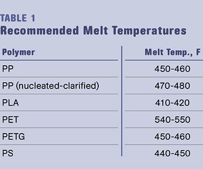
An overall tighter level of control for a thin-gauge extrusion system is paramount (from the extruder barrel through the die) while keeping the chrome-roll temperature settings high enough to prevent rapid freezing on the middle roll. Typical melt temperatures required for various polymers are shown in Table 1.
3) Die-lip exit to roll-nip distance
Ideally, it is always desirable to operate with minimal die-lip exit distance to the entrance where the primary nipping rolls meet. Minimizing this distance subsequently minimizes the adverse effects of pre-skinning (rapid freezing) of the molten polymer and excessive neck-down of the melt “curtain” that will eventually form into the rolling melt bank. At the same time, this permits greater overall control and formation of melt-bank uniformity.
There are constraints that must be managed to minimize this physical distance. The blunt cross-sectional profile of the sheet die is one limiting factor. Externally protruding sheet-die deckles and/or appendages are other factors, along with the physical size (diameter) of the chrome rolls.
The sheet die can be profiled by using a contoured body so it fits closely into the mating chrome rolls. Internal and/or “pinch” shim deckles may be used to control the curtain width entering the nipping area while avoiding protrusions from the die surface, so as not to force the distance to widen. Pinch shim deckles reside between and inside of the lips and are usually made of aluminum shim stock to suitably fill the die-lip gaps. Another technique is to reduce the leading roll diameter so that the gap is minimized.
As a general rule of thumb, this distance should range from 100 to 200 mm (4 to 8 in.) depending on the size of the components being used.
4) Targeted sheet width & die deckling
Several accepted practices are used for limiting the overall width of the molten polymer curtain that exits the sheet die and forms the rolling melt bank between the nipping rolls. Internal and pinch shim deckles are mentioned above as effective deckle methods. External deckles are also commonly used, but they protrude from the face of the sheet die, which increases the die-exit to roll-nip gap distance. In addition, increasing this distance while increasing the overall line speed for the roll stand will reduce the width of the molten curtain due to the phenomenon of “drawdown.”
By drawing the sheet width down, the thickness of the melt curtain will increase along with the edge bead that subsequently forms. This is not a desirable outcome for thin-gauge sheet processing because it creates more problems than it solves. Difficulties include excessive sheet orientation, which can lead to dimensional stability issues, and heavy sheet-edge gauge bands that make it difficult to maintain a uniform melt bank and properly polish the sheet across its entire width.
5) Roll construction and quality
Suitable roll design and construction are essential when operating at higher roll loads. Thin-gauge sheet production requires high-quality rolls and a system capable of operating at high roll loads with precision. Especially critical are the roll journal and bearings. C1 spherical tapered roller bearings provide the best operating precision, yielding a total indicated run-out (TIR) of 0.0005 in. or less. Roll shafts and bearing journals must be designed accordingly. The overall roll shell construction and style must accommodate precise rotation while under extreme loads. Required roll loads as high as approximately 1000 PLI (lb/linear in.) are not uncommon in processing thin-gauge sheet. High-quality roll finishes are also essential to reduce the variability found in coarser roll-finish treatments. Typically, a highly polished chrome super finish of 0.5 Ra is recommended.
6) Roll closing forces & nipping loads
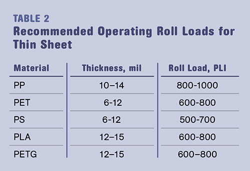
Table 2 summarizes the recommended operating roll loads required to produce consistent thin-gauge sheet. To generate suitable operating roll loads so that the rolls remain closed, a boosted pneumatic or hydraulic roll-actuation method is recommended. Inadequate load generation will prevent the rolls from holding the desired gap and a poor outcome will result.
7) Counteracting roll deflection
The overall design and quality of steel chrome rolls will determine the degree of deflection realized when placed under load. Higher loads will result in greater deflections. The level of deflection may be significant when compared with the target gauge desired and can result in an inability to produce high-quality sheet. A deflecting roll will cause a relatively high gauge band to form in the center of the sheet, coinciding with the deflection pattern that is being produced. For example, if the sheet gauge target is 10 mils and the resultant roll deflection is 3 mils, the net variance is an unacceptable 30% above the target gauge. A reasonable gauge performance would be ± 3% of target throughout the range of thinner sheet gauges.
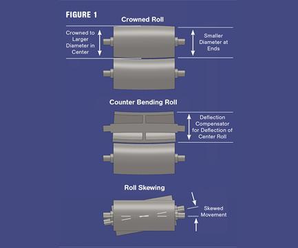
There are three basic methods for counteracting the adverse effects of roll deflection (see Fig. 1). A crowned roll features a pre-ground camber to the roll. While this technique is effective, it is limited to a narrow range of products since the geometry of the camber is fixed and limits the operational deflection conformity to a reduced processing window.
Counter-bending rolls have designs that attempt to bend the roll in an opposite direction to the load such that it conforms to the mating roll and thus minimizes the effects of the deflection pattern. This technique also limits the overall effectiveness across a wide operating range. Roll loads less than 800 PLI are required due to the spring constant and mechanical limitations of the operating window for this type of roll design.
Finally, roll skewing employs a cross-axis positioning of the roll such that the roll deflection is wrapped about the mating roll, thus creating a uniform gap over a wide operating range. Considering the universal operating range for processing thin-gauge materials, the roll skewing technique is highly versatile and therefore recommended. The adjustability feature operates over a wide range of deflection patterns and subsequent sheet gauge targets.
8) Minimizing sheet sag & droop
The attitude of the sheet die relative to the roll stack will affect the direction in which the molten curtain exits the die due to gravitational effects. There are several varieties of roll-stand configurations, and each has its merits and limitations. The vertical roll stand is widely used and has the greatest level of versatility across a wide operating window of sheet processes. Yet it is not the best configuration when attempting the thinnest sheet gauges, as the gravitational effects are extreme, causing sag and droop and leading to rapid freezing and pre-skinning of the melt bank on the middle roll.
A J-stack arranges the roll stand so that the die attitude approach is at a 45° angle. This method permits a reduction of gravitational effects and provides a greater center-roll wrap due to the unique web path that results. However, there is a tendency for the melt curtain to droop onto the lower roll in this up-stack arrangement, whereby the web path traverses upward throughout the roll stand.
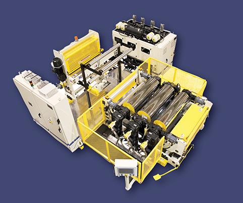
A third configuration is a horizontal roll stand. While this configuration is recommended for superior thin-gauge results, it also has operational limitations and constraints due to its geometry when processing heavier gauges.
The horizontal roll stand eliminates the adverse effects of sag and droop and permits introducing the melt bank precisely and directly into the primary roll nipping location as shown in the photo. This allows the operator a greater range of processing when attempting the challenges of thin-gauge sheet production, particularly when processing tenacious materials that otherwise can present challenges with other roll-stand configurations.
9) Controlling the melt bank position
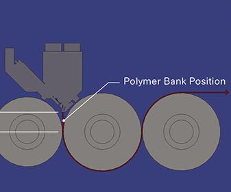
No matter which roll-stand configuration is used, controlling the melt-bank position is essential to avoid the adverse effects of rapid freeze-off and pre-skinning of the melt bank (see Fig. 2). Often an experienced operator will adjust the height of the roll stand relative to the die-lip exit to permit running the melt bank against the middle roll. This reduces the adverse effects of rapid freeze-off and pre-skinning while also negating the adverse effects of sheet sag and droop.
An external air bar provides an excellent tool for precisely positioning the melt bank by flipping it from one roll to the other. The melt bank will seek the flowing air, thus placing it against the middle roll. In the case of a vertical roll stand, the air bar would be beneath the sheet die, blowing upward against the middle roll towards the pool of the melt bank at the nipping location.
10) Accurate speed control
Precise speed regulation and coordination are essential in producing high-quality thin-gauge materials of all resin types. With a good digital drive control platform, roll-to-roll speed coordination should be on the order of ± 0.01% of setpoint. This becomes an important factor, since the processing window is narrower on these materials and therefore requires a higher overall level of coordination and control precision.
Matching the roll speeds from roll to roll is critical to ensure minimal orientation is being introduced between the rolls. It also balances the roll-stand take-off speed, which will minimize the adverse effects of drawdown at the die exit. Proper tension control between the main chrome rolls and pull-roll unit will also minimize formation of unwanted transverse-direction lines in the sheet in the form of faint chatter marks and will avoid introducing orientation from stretching the sheet. This tension should be maintained in a range of 2 to 4 PLI across the width of the sheet.


Related Content

The Importance of Viscosity in Melting
The calculations required to determine the right melt temperature for each polymer are complicated. Knowing the power-law coefficient and the consistency index of the polymer you run might prove useful.
Read More
Understanding Melting in Single-Screw Extruders
You can better visualize the melting process by “flipping” the observation point so that the barrel appears to be turning clockwise around a stationary screw.
Read More
Specialty Purging Compounds Optimize Color and Material Changeovers
Selecting of the correct purging compound can speed up material and color changeover time and reduce scrap. You’ll even save on material.
Read More
How Polymer Melts in Single-Screw Extruders
Understanding how polymer melts in a single-screw extruder could help you optimize your screw design to eliminate defect-causing solid polymer fragments.
Read MoreRead Next

Lead the Conversation, Change the Conversation
Coverage of single-use plastics can be both misleading and demoralizing. Here are 10 tips for changing the perception of the plastics industry at your company and in your community.
Read More
Why (and What) You Need to Dry
Other than polyolefins, almost every other polymer exhibits some level of polarity and therefore can absorb a certain amount of moisture from the atmosphere. Here’s a look at some of these materials, and what needs to be done to dry them.
Read More