
Take These Steps To Maintain Efficiency Of Your IBC
The overall performance of a blown film line depends on a properly tuned and maintained IBC control system. Follow these preventive-maintenance tips to keep your system running smoothly.
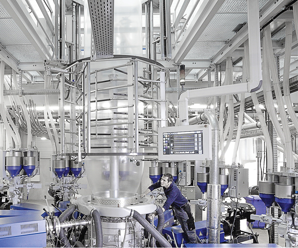
Processors running advanced blown film lines are well aware of the advantages of using IBC boost to production, like a turbo charger does for a car. But proper maintenance is required to keep any IBC system running optimally. (Photo: Reifenhauser)
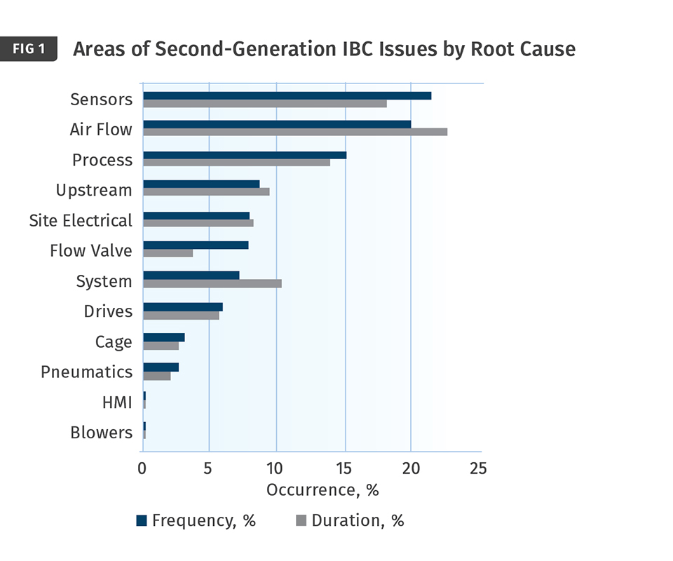
Shown here are the various root causes of issues with second-generation IBC systems, compiled from 780 calls taken by D.R. Joseph. In terms of frequency, the number-one problem area was sensors.
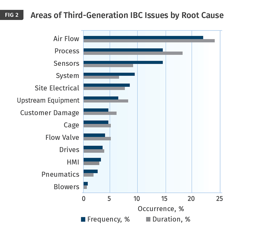
An effort to make the sensor communication process more robust and noise resistant in D.R. Joseph’s third-generation system was successful. Both frequency and duration are down significantly when compared with the second-generation system. This data is based on 275 service calls taking 182 hr of tech support time.
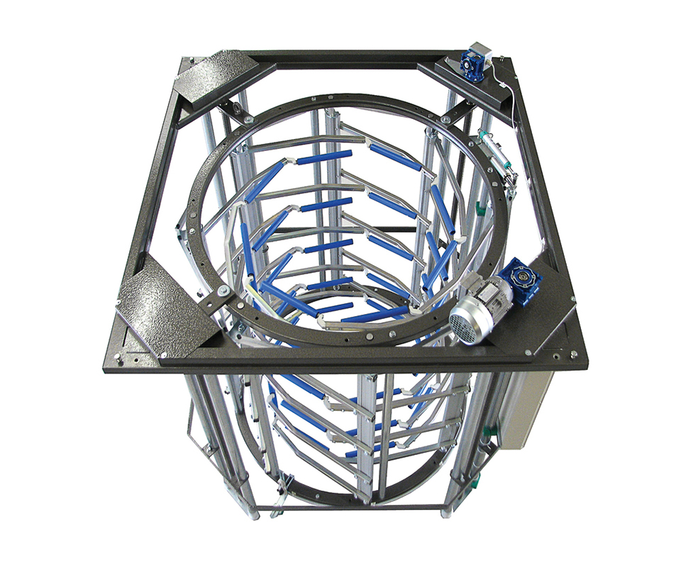
On bubble cages, new-style soft rollers ensure no negative impact on film quality. For IBC systems that control the bubble-cage open/ close position, a smooth, consistent movement is required to meet today’s layflat-control standards.
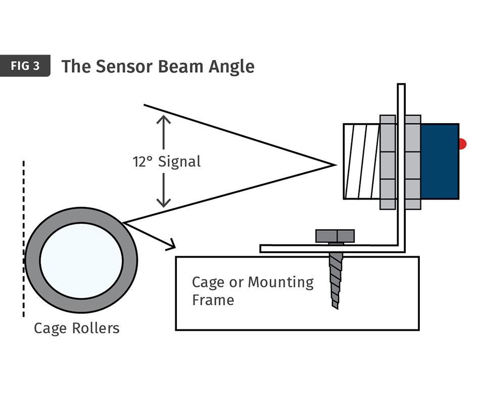
There must be no obstructions—cage or stabilizer—to the sensor path that might interfere with the signal. The typical ultrasonic sensor has an included beam angle of 12°. As the distance from the sensor to the bubble increases, the area of the clear path required increases as well. At a distance of 175 mm, the clear area required is on the order of 38 mm. For layflat-detection sensors mounted on top of the bubble cage, the clearance has to be considerably larger.
At least annually (and after any work that requires ducting disassembly), walk the supply and exhaust air-flow path, checking and listening for leaks with the blowers running at least 70% of maximum speed.
Flow-control valves must be calibrated to the flow backpressure generated by the narrow air paths through the die. This is so the valve has the maximum linear operating window to provide optimum performance over a large range of operating conditions.
Most IBC blowers are arrangement 4 pressure type with motor, housing, and impeller. Maintaining blowers takes very little work, but not doing the work can be very costly in terms of lost production and very time consuming, particularly if you have to reopen the blower housing.


For blown film processors, taking advantage of internal bubble cooling (IBC) is very desirable and quite easy. Anyone can purchase a blown film line that includes IBC as standard equipment or an option. IBC provides the same boost to production as a turbocharger for a car, at relatively low added cost, so not using IBC leaves one at a competitive disadvantage.
For new adopters or those with little IBC system experience, preventive-maintenance (PM) action items are often ignored and omitted from the schedule. Ignoring IBC PM tasks is so common because most of the critical elements of IBC are “invisible.” Maintenance staff often thinks of the IBC system as a mysterious black box not to be touched for fear of messing it up. It really does not need to be that way.
The premise of this article is that achieving optimum performance of an IBC system is directly linked to proper care and maintenance of the system, including the “invisible” portions. As an IBC system supplier for more than 27 years, D.R. Joseph, Inc. has seen a lot of IBC issues over the years. Last year, the company decided to redo a study conducted in 2005 to see if anything had changed in the areas where problems occur and how long it takes to solve those problems. Our interest was to use this information to guide our R&D development process. Of course, the information can also be used in identifying PM tasks that will be likely to keep the system running optimally, which is the main purpose of this article.
Figure 1 shows the various root causes that resulted in a customer calling us for technical support. The data is from 780 calls taken for D.R. Joseph’s second-generation IBC system between 2006 and 2014. Of the areas listed, several need a short explanation:
• Process: These are issues with an extrusion process variable— for example, excessive melt temperature.
• Upstream (and Downstream) Equipment: These are issues that pertain to extruders, primary nips, collapsing frames, and air rings. Unsteady speed or improper setup for these items is a common problem.
• Site (Electrical): These are issues of power loss, phase loss, ground faults, and floating neutrals, which cause a whole host of strange issues too numerous to list.
Notice that for the second-generation IBC systems, the number-one root-cause area was sensors. This is fairly common because the sensors take incredible abuse from ambient and radiant bubble heat, misalignment from object strikes (sometimes an operator’s head) and operating 24/7 year after year. Sensor communication signals are also a source of issues from damaged cables, wires
pulled out of the back of the sensor, and induced signal noise.
Figure 2 shows that an effort to make the sensor communication process more robust and noise resistant in D.R. Joseph’s third-generation system was successful. Both frequency and duration are down significantly when compared with the second-generation system.
So taking the third-generation list as the priority sequence, let’s review what it takes to keep air flow, sensors, system, cage, flow valve, drives, HMI (operator interface), pneumatic, and blower issues down to a minimum with preventive-maintenance actions.
AIR-FLOW PATHS
The air-flow path is the single most problematic portion of the IBC control system in terms of both frequency of issues and their resolution time. The heart of the matter is the very low pressure inside a blown film bubble makes width control a very delicate matter. Ideally, none of the blower-generated air flow should escape into the atmosphere until reaching the exhaust blower. In practice, this rarely happens, as small leaks are tolerated as long as they are before the flow valve.
Here are the PM items for air-flow paths:
1. At least annually (and after any work that requires ducting disassembly), walk the supply and exhaust air-flow path, checking and listening for leaks with the blowers running at least 70% of maximum speed. In a noisy plant this is difficult to do by ear, and is even more difficult if the duct is covered in insulation, but it is possible to see or hear issues by looking at ducting irregularities and checking near duct connection points. As a secondary note, avoid the use of spiral ducting, which leaks air and polymer residue.
2. Check and clean filters on a monthly basis. These include filters inside the cooling coils.
3. Annually, open the access covers for the cooling coils and inspect the coils for scaling or dirt buildup, which reduces air flow through the coils. You can use a differential magnehelic to provide an indication that the pressure drop across the coils has increased to unacceptable levels. A typical normal differential pressure is less than one inch of static pressure.
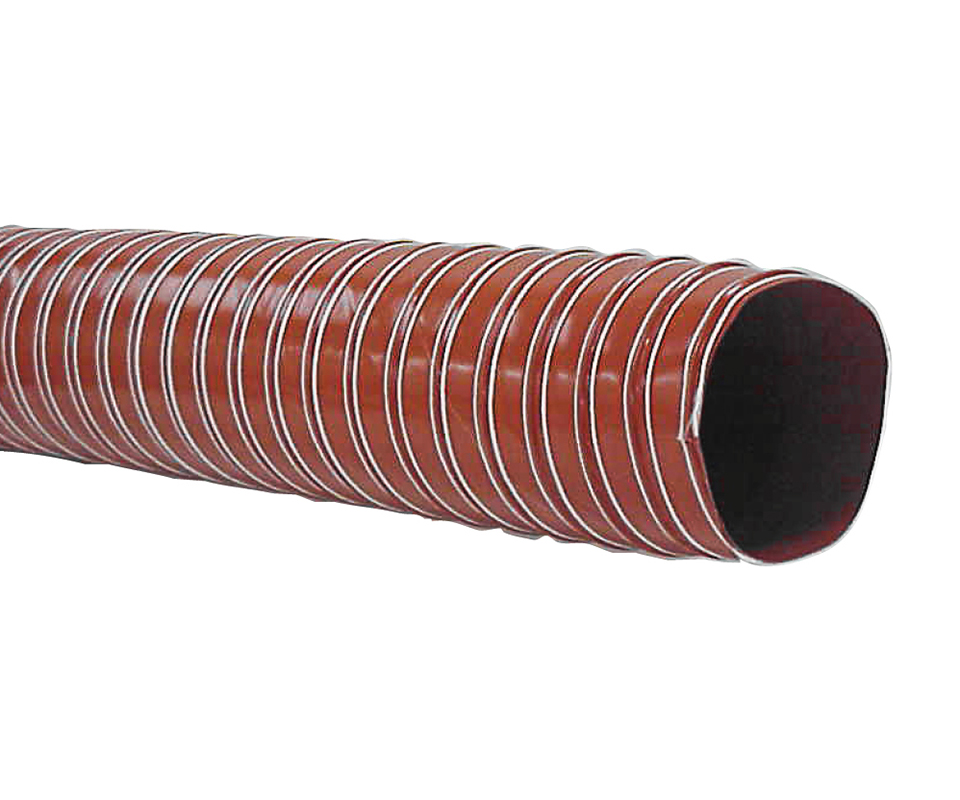
4. Once a year, replace the flexible hoses connected directly to the die. This is because the connection point at the die gets very hot and decomposes even the best flexible hose over a year’s time. If time and budget are an issue, replace only the exhaust hoses. Use silicone-based hoses with smooth internal surfaces and that can handle up to 500 F (260 C). Hoses near heavy foot traffic often get stepped on and damaged. Consider mechanical protection for these hoses. Also, avoid sharp bends in flexible ducting and mitered metal elbows. Both will reduce air flow, which translates into production losses. Flexible ducting takes a lot of stress and heat and often fails internally without visual indication externally. Don’t be afraid to remove a perfectly good looking section of flexible hose so you can see the inside.
5. On an annual basis (or semi-annually if you run recycled materials), remove the IBC hardware from the top of the die and verify that all air-flow paths have no buildup of polymer residue in the air pipes. Clogged pipes are the most damaging problem for the system's performance, much the way that clogged arteries will end one’s life faster than a weak heart. During reinstallation, double-check that you have cooling hoses going to cooling pipes and not mixed up with heating pipes. Also make sure the die-mounted hardware is assembled correctly. Check after assembly by turning on the cooling blower and removing an exhaust hose. There should be no air flow coming from the exhaust hose.
6. Finally, check the exhaust chimney for accumulation of plastic. Since the exhaust chimney is essentially a long vacuum hose, it is common after a bubble break for film to be pulled into the chimney unless there is a screen cap atop the chimney.
SENSORS
IBC sensors can be problematic if operating guidelines are not maintained. With proper care and alignment, these bubble sensors can last 5-7 yr. The mode of failure for an ultrasonic sensor is generally a slow, gradual decrease in sensing accuracy. However, a swift end to the sensor can occur when mechanical damage occurs, particularly when the damage is to the sound-emitting portion of the sensor.
The keys to proper bubble sensing are alignment and positioning the sensor within its operating range. Ultrasonic sensors require straight line-of-sight alignment with the bubble. The most common failure with sensors is alignment, as sensors can
misaligned from snagging by an unstable bubble.
Use this as a PM guide for sensors:
1. Visually inspect sensor alignment and body integrity on a weekly basis. As the most common sensor issue is misalignment with respect to the bubble, make sure all the sensors are properly pointing at the bubble. If the face of the sensor is damaged, the sensor will not function properly. If the body of the sensor is somehow crushed or the cable pulled out of the back, the sensor should be replaced. Most sensors have an external LED, which will be illuminated with power or echo detection. Verify proper operation of the LED, as it could point to an alignment issue or sensor failure. For sensors without status LEDs, the system touchscreen is usually the device by which sensor operation is checked.
2. Check for obstructions to the sensor path. The typical ultra- sonic sensor has an included beam angle of 12°. As the distance from the sensor to the bubble increases, the area of the clear path required increases as well. For instance, at a distance of 175 mm, the clear area required is on the order of 38 mm. But for layflat-detection sensors mounted on top of the bubble cage, the clearance has to be considerably larger.
3. Once a quarter, check the sensor cables for damage, exposed wires, loose connectors. Sensor cables should not be hanging from the back of the sensor or in a position that allows the bubble to snag the cable.
4. Replace sensors that are more than seven years old. The older the sensor gets, the weaker it gets, and eventually it cannot sense the bubble at longer distances. We see this over and over: sensors 10 to 20 years old and still in production. Sounds like a good thing, but the production rate is suffering as a result.
SYSTEM
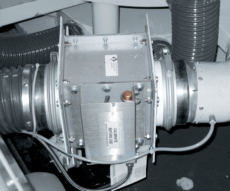
System refers to the main controller that manages the inputs and outputs required for IBC control. Inputs come from the operator via a touchscreen in the form of layflat target setpoint, air-exchange rates and pressure the bubble creates when contacting the bubble-cage rollers (referred to as cage contact). Outputs are to the variable-speed drives (to manage air exchange), the flow valve (to manage bubble position relative to the cage), and the bubble cage (to manage layflat width).
Here are the PM items designed to reduce issues with the system controller:
1. Check the CPU backup battery annually to ensure it is still working. CPU battery backup is designed to maintain critical data required by the CPU to start after a shutdown (planned or otherwise). Note that lithium- ion batteries will operate properly for roughly 7-10 years if power remains on 24/7 (except for power failures or maintenance shutdowns). Extended powered-off periods will significantly shorten battery life. Some systems will not restart after a power loss with a dead CPU battery.
2. Verify the controller parameters. Every controller has a set of parameters used to manage how the system responds to the pro- cess. Parameters allow customization and provide flexibility for processing different products. Company standard operating procedures should include a periodic review of parameters on process-control devices for which operators can access the parameter settings. Ask your IBC system vendor to see if it has a method of easily verifying that all parameters are unchanged relative to an established standard.
2. Every two to three years, use the system testing facility to verify operation of the system inputs and output signals. Check with your IBC supplier for instructions on how to perform this task.
BUBBLE CAGE
The bubble cage is what stabilizes the bubble over the air ring to ensure the cooling ring can provide a perfect flow of air over the outer surface. New-style soft rollers ensure no negative impact on film quality. For IBC systems that control the bubble-cage open/ close position, a smooth, consistent movement is required to meet today’s layflat control standards.
The key to keeping the cage working properly is periodic inspection of the various components:
1. Rollers: Inspect the rollers quarterly to make sure they are moving smoothly and without cuts in the roller surface, which will transfer marks to the film.
2. Arm alignment: Inspect arms quarterly to ensure all are parallel to each other.
3. Cage alignment: Whenever the die is removed and reinstalled, drop a plum bob from the center of the haul-off (when closed) and adjust the die position to ensure proper centering. Do this with the extruder adapter pipes hot. Once that is done, check the cage arms for centering and correct as needed.
4. Cage diameter-control motor: Once a year, inspect this motor, making sure the cage opens and closes smoothly over the entire range of motion, and make sure limit switches are activating before the mechanical limit of the cage. Check again the arms for interference with other arms. Test and tighten all loose linkages to eliminate backlash, which makes size changes more time consuming. Replace worn linkages connecting shoulder bolts.
5. Cage elevation screws: Annually, make sure the brass bearings that support the cage are in good shape by greasing as per the manufacturer’s recommendations. Double-check that the cage is level and check the chain tension that controls the individual screws that turn to lower and raise the cage. If the cage is not level, one or more of the elevating screws has jumped a tooth and will have to be retimed.
FLOW VALVE (INCLUDING PNEUMATICS)
The flow valve is the main control element for keeping the bubble in the correct position relative to the bubble cage. Flow-control valves must be calibrated to the flow backpressure generated by the narrow air paths through the die. This is so the valve has the maximum linear operating window to provide optimum performance over a large range of operating conditions.
Here are the flow-valve PM items:
1. Monthly, verify there are no leaks between the air-flow valve and the die. Leaking air between these two points will reduce the system layflat control capability by up to 20 mm.
2. Monthly, inspect the pneumatic regulator (if supplied) for proper pressure and the presence of water. Water condensate that exceeds the regulator’s collection capacity will enter into the flow valve and dramatically change the response and layflat-control capability. Diagnose the source of the water or the repair will be needed repeatedly. The presence of water may damage some pneumatic pressure devices; so have it checked before restarting the line.
3. Semi-annually, do the valve calibration process as specified by the system manufacturer. Make sure the IBC supply blower is operating properly and the impeller is rotating in the correct direction prior to calibration.
4. Every two or three years, remove the valve from the ducting to check for buildup of dirt, debris, or other foreign objects that may restrict air flow or valve movement.
VARIABLE-SPEED DRIVES
Variable-speed drives manage the internal air exchange by supplying high-pressure cooling and exhaust air with separate blowers. Newer drives are very reliable but when problems do happen, locating the root cause can be difficult.
Here are the PM items to follow:
1. Annually, check the fault-history log of each drive to determine if a drive is experiencing periodic difficulties. Operators and maintenance personnel tend to reset drives without diagnosing the root cause of the failure. Fault logs will show recurrent issues, which need to be attended to before the drive or motor fails completely and causes extended downtime.
Look for:
a. DC bus overvoltage caused by excessive deceleration.
Verify deceleration settings.
b. Phase loss caused by incoming power problems.
Check the main supply.
c. Motor overheating, often caused by wrong nameplate
details entered into the drive (don’t overlook the possibility that the motor is truly overheating).
d. Drive overheating caused by a failing or dirty drive-cooling fan or inadequate panel ventilation.
2. Any replaced drive must be reprogrammed exactly as the IBC supplier states in its documentation. Failure to do this can result in DC bus overvoltage situations, as drive manufacturers default to typically 3 sec on the acceleration and deceleration. IBC systems with flow valves do not need this rapid response, but systems without flow valves indeed require faster response and typically require braking resistors. In either case, getting the drive parameters set properly is paramount for good IBC control.
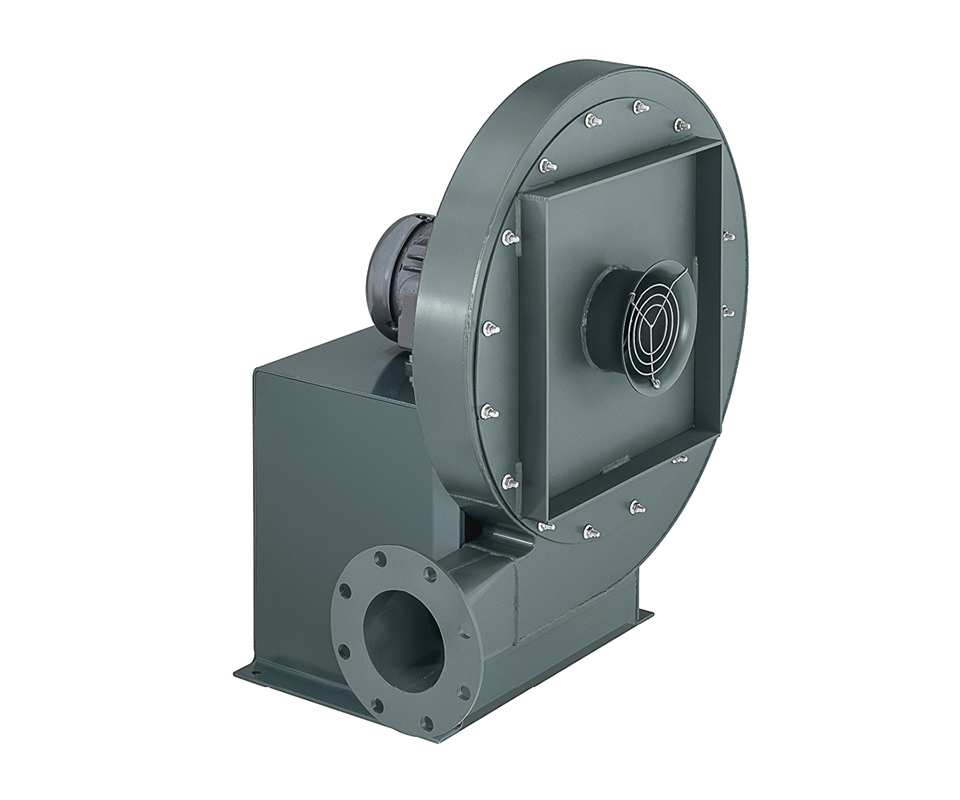
BLOWERS
Most IBC blowers are arrangement 4 pressure type with motor, housing, and impeller. Maintaining blowers takes little work, but not doing it can be very costly in terms of lost production and very time consuming, particularly if you have to reopen the blower housing.
PM items for pressure blowers are:
1. Rotation: The impeller will create pressure in both directions; so whenever there is any maintenance on the blower motor or the variable-speed drive, rotation must be double-checked.
2. Impeller-to-motor integrity: Whenever there is any work on the motor, the impeller must be removed. The locking collar must be replaced and properly tightened with the key installed.
3. Greasing the motor bearings: Follow the manufacturer’s recommendations for the type of grease and greasing intervals. Blower motors have two bearings. The outer bearing fitting is typically easy to access; the inner requires a grease gun with an extension.
The overall performance of any blown film line depends on a properly tuned and maintained IBC control system. IBC control is just a machine like any other, except most of what it does is invisible to the human eye. Your inability to see air disturbances, ultrasonic waves, or other hidden details does not excuse you from maintaining a system that is responsible for up to 50% of added production capacity. Diligently following the PM items here will keep the system running smoothly for years.
ABOUT THE AUTHOR: Daniel R. Joseph founded D.R. Joseph, Arlington, Tex., in 1987 to supply the blown film industry with engineering support. That idea grew over the years into patented innovations, which resulted in DRJ becoming a global leader in blown film bubble-management systems. His current activities include R&D efforts for product development and training systems. He also runs the North American service and support operations for Kundig International, a company specializing in thin-film thickness-measurement systems. Contact: (817) 987-2030; danielj@drjosephinc.com; drjosephinc.com.


Related Content

Cooling the Feed Throat and Screw: How Much Water Do You Need?
It’s one of the biggest quandaries in extrusion, as there is little or nothing published to give operators some guidance. So let’s try to shed some light on this trial-and-error process.
Read More
How Much L/D Do You Really Need?
Just like selecting the extruder size and drive combination, the L/D should be carefully evaluated.
Read MoreWhy Compression Ratio is Important
Compression ratios have been pretty much standardized over the years, based on what has typically worked before. But there are quite a few variables that must be considered in order to get the optimum performance from your screw.
Read More
How to Estimate and Control Head Pressure
You rightfully worry about melt temperature, but don’t overlook head pressure, because the two are closely linked and will influence line performance.
Read MoreRead Next

Advanced Recycling: Beyond Pyrolysis
Consumer-product brand owners increasingly see advanced chemical recycling as a necessary complement to mechanical recycling if they are to meet ambitious goals for a circular economy in the next decade. Dozens of technology providers are developing new technologies to overcome the limitations of existing pyrolysis methods and to commercialize various alternative approaches to chemical recycling of plastics.
Read More
People 4.0 – How to Get Buy-In from Your Staff for Industry 4.0 Systems
Implementing a production monitoring system as the foundation of a ‘smart factory’ is about integrating people with new technology as much as it is about integrating machines and computers. Here are tips from a company that has gone through the process.
Read More