
Take These Steps to Optimize Your MFR Data
Make your life easier by paying close attention to the procedural steps detailed in the test standards.


If you use an extrusion plastometer (melt indexer) to test the melt-flow rate (MFR) of resins, you can make your life a whole lot easier by paying close attention to the procedural steps detailed in the test standards, to ensure accuracy, efficiency and smooth operation. This is true whether you are conducting occasional tests or running extensive automated testing in a lab setting. Many say they meet a published test standard, but in reality they are not following the test standard exactly as written.
The melt-flow test is a measure of the mass of material that is extruded through a standardized orifice in a die under standardized temperature and load conditions; the results are expressed as g/10 min. It is a common test used in the plastics industry. Values obtained from the test are useful to processors for material selection and processing machine setup. The test is described and defined in ASTM D1238 (Standard Test Method for Melt Flow Rates of Thermoplastics by Extrusion Plastometer) and ISO 1133 (Determination of the melt mass-flow rate and melt volume-flow rate of thermoplastics). The standards are similar but there are equipment and procedural differences that may produce differing results.


Here, we focus on the ASTM D1238 procedure. Both standards describe a manual cut-and-weigh type test, known as Procedure A and a more automated test, known as Procedure B.
It is important to remember that standards can change over time, based on real-world input from the many members of various industry associations like ASTM. In fact, the ASTM standard for melt flow was recently revised. That is why it is important to stay involved in the industry and to always be sure you are working with the latest version of any standard. An updated version of the D1238 was released in 2020. It can be downloaded from www.astm.org for a small fee. It is good practice to review the latest version of the standard before testing, regardless of whether you are a new user or an experienced testing veteran.
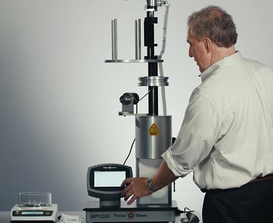
The author demonstrates a Procedure B MVR test.
The melt indexer is basically a furnace that contains a heated metal cylinder with a bore drilled through it. The bore has specified dimensions and finish. At the bottom of the bore is a removable die with an orifice. The dimensions of the die are also specified. Material is heated in the furnace and driven through the orifice by a piston (plunger). A mass is applied to the piston which, along with gravity, forces the material to extrude. The temperature is controlled to within ±0.2° C at 10 mm above the die and ±1% of the setpoint 75 mm above the die.
The mass applied to the piston is material dependent and may vary, depending on required test conditions. Most modern machines are equipped with a built-in timer and are provided with the necessary tools to conduct a test. Optional accessories include a displacement-measuring device, necessary for Procedure B testing. These accessories can help automate the test and reduce variability from operator to operator.
The goal of the test is to allow the piston to develop a steady-state flow and get to the test start point within the window of time allowed by the standard. Before a test measurement can be made, the material is loaded in the bore of the cylinder in the furnace and then subjected to a preheat period in order to melt the material thoroughly and allow any trapped air to escape. Data is collected at a specified starting height over a defined stroke of piston travel.
The preheat period begins after the material is charged and the piston is reinserted into the bore, and it ends when the piston foot reaches a specified height in relation to the top of the die. At that point, the operator, begins the actual test. How the test is conducted depends on whether Procedure A or Procedure B is being used.
The Test Setup
Regardless of which procedure is used, the operator plays a key role. The machine must be set up properly and kept clean, and adjustments and settings need to be made to the machine and test procedure based on the expected flow rate of the material. The first decision an operator needs to make is which procedure to use. Procedure A is simply a collection of the mass of material that flows out versus time. To prevent thermal degradation of the material under test, the actual test time is only a fraction of the 10 min reported, usually only 60 sec. However, the actual test time varies with the expected flow rate. High-flow materials are collected in less time, while fractional melts require more time to collect a useable sample. The mass collected is then multiplied by the appropriate number necessary to convert to the final reported value in g/10 min.
Procedure A is simply a collection of the mass of material that flows out versus time.
Procedure B employs encoder technology to precisely measure piston position and travel. Since the volume of the bore is specified, the volumetric flow rate of material (MVR) is determined in cm3/10 min. The MVR is converted to MFR by multiplying the MVR by the material’s melt density. The melt density (g/cm3) is defined as the density of the material when it is in its molten state. If you are testing virgin polyethylene or polypropylene, you can use a generic value for melt density given in ASTM D1238. For all other materials, you will have to determine the melt density using a combination of Procedure A and B. Melt-density values change with processing and additives.
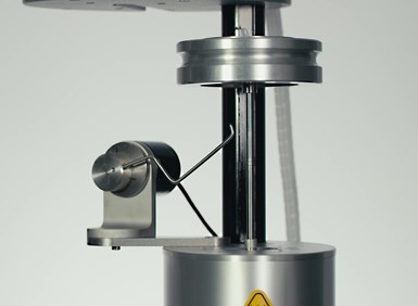
Procedure A test with a weight attached during the 7-min preheat as defined in the standard.
While there is no consensus on which procedure is best, Procedure A is typically most useful for organizations that test infrequently, use a wide range of materials, use different additives in their materials, or use regrind/recycled material. You can use Procedure A on materials that have flow rates under 50 g/10 min. Procedure B is best suited for labs that test the same material repeatedly and for higher flow materials. It reduces the amount of operator involvement but does not eliminate it.
The next decision an operator must make is how much material to charge in the machine. The charge weight will vary based on the expected flow rate of the material. Some guidance on charging weight can be obtained from ASTM D1238. In reality, it will take some experimentation to determine the proper charge weight that will result in the piston being in the proper position at the end of the preheat period.
Procedure B employs encoder technology to precisely measure piston position and travel.
Again, the goal is to obtain a steady flow by the time the capture period starts. The amount of material charged in the cylinder will be less if the material has a low melt flow. It is important that the right amount be charged so that purging can be avoided, if possible. (Technically, purging of excess material is allowed, but not in the last 2 min of the preheat period. Experience has shown that the force applied while purging will vary from operator to operator, and it can affect results for some materials. Purging can be avoided if the proper charge weight is used. Conversely, higher flow materials will require more material.
The Preheat Period
Both procedures require a preheat period. The purpose of the preheat period is to allow the material to melt completely and to allow trapped air to escape. The preheat period begins after the piston is re-inserted into the cylinder after charging the sample, and it ends when the first capture, or test measurement, begins. Since the mid 1990’s, ASTM D1238 has required a preheat time of 7 min ±30 sec (i.e., 390-450 sec).
The operator must then decide when to place the test load onto the piston. If the weight is applied too soon, all the material may flow from the cylinder before the end of the preheat, resulting in no material being left to test. Either the application of additional weights to the piston to complete the test load must be delayed or the load needs to be supported. This can be done using the machine, if equipped with a weight support, or the weights may be supported with a removable block. In cases where high-flow material is being tested, it will be necessary to delay application of the test load until the preheat time expires.
Additionally, the orifice in the die may need to be mechanically plugged to prevent any flow during the preheat period. In some cases, a small load may need to be applied to keep the piston from being forced out of the top of the bore due to material expansion while heating.
The Test Measurement
Experience has shown that taking measurements when the piston is at different heights within the bore will result in differing test results. That is why a start height is designated in the standard. The test starts when the leading edge of the piston (bottom of the piston foot) reaches a point in the bore where it is 46 mm (1.811 in.) above the top of the die. The ASTM D1238 piston rod has two scribe lines engraved on the shaft. The center of the scribe lines indicates when the bottom of the piston foot is 46 mm (1.811 in.) above the top of the die. During a Procedure A test, the operator must observe the position of scribe lines in relation to the guide collar. When the bottom scribe line disappears into the guide collar, its allowable, according to the standard, to make the first cut, ending the preheat period and starting the test. Just make sure to make the cut before the top line disappears.
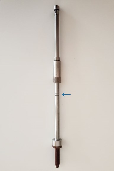
The arrow pointed at the center of scribe lines designates ASTM D1238 start point.
When the start point is reached, the operator must make a clean cut of the material along the bottom of the die as the material exits the orifice, while simultaneously starting a timer. The material extruded during the preheat period is discarded. The length of time of a capture varies with the expected flow rate. Guidance can be obtained from ASTM D1238. A typical time interval for the test is 60 sec. At the end of the capture period, a final cut is made. The amount of material extruded out of the die during that 60-sec time-period is then weighed and the multiplied by 10 to report the flow rate in g/10 min.
The cutting technique should result in a clean cut of the extrudate, avoiding strings or material sticking to the underside of the furnace, if possible. It should be done at precise intervals, corresponding as closely as possible to signals from the timer. It is an acquired skill and may seem awkward at first. Automatic cutters can be used, but they may not work with all materials. The ASTM method requires a single cut be made for the test result.
For Procedure B tests, the operator must decide on the travel distance for the test. D1238 allows for either 6.35 mm (0.25 in.) or 25.4 mm (1 in.) of travel. Lower flow rates, generally under 10 g/10 min, use the shorter distance. The amount of material charged is the same as in Procedure A. The beauty of Procedure B is that if the machine is set up properly, a result is generated without further involvement of the operator, as a properly calibrated machine will know where the bottom of the piston foot is in relation to the top of the die.
The piston displacement on many modern melt-flow indexers can divide up the 6.35- and 25.4-mm travels into discrete measurements, if desired. It is important that the test result be reported as an average value of the captures taken over the 6.35 or 25.4 mm of travel, not as individual values. If the test material is subject to air bubbles, this technique can be useful to eliminate captures spoiled by the trapped air.
The importance of cleaning the machine properly cannot be over-emphasized.
Cleaning Up
After a test is completed, the remaining material must be purged from the bore and the equipment needs to be cleaned. The importance of cleaning the machine properly cannot be over-emphasized. Some materials are easily cleaned from the machine while others present challenges. After the remaining material is purged from the bore, the piston rod and the die are removed from the bore and wiped down with a cotton cleaning rag. Both items should be cleaned down to bare metal.
The orifice in the die is cleaned with an orifice cleaning tool. Copper gauze or industrial abrasive pads work well to prevent residue from building up and causing the components to become out of dimensional tolerance. It is good practice to wipe with cotton rag as a final cleaning step. The worst of the residue can be cleaned from the bore with cotton cleaning patches. Brass brushes may be used to remove stubborn residue. When pared with a cordless drill, the brass brush is highly effective. The bore should have a mirror finish, without any smudges or scratches. Using solvents or other chemicals to clean melt-indexer components should be avoided, because residue can remain on the surface and affect the results of subsequent tests. After cleaning, the die and piston should be reinserted to make sure they are at temperature prior to the next test.
How you run your test depends on how your machine is equipped. Most melt indexers are available with optional features and accessories to do additional testing procedures not covered in this article. Some materials require special treatment, like drying, before testing. Some melt testing applications call for more sophisticated data collection and storage, so most plastometers are designed to work with external testing software programs. Such software typically can store an unlimited amount of test settings and test results for easy recall, and there are usually more elaborate capabilities for generating test reports and SPC control charts. Contact your machine manufacturer for setup and maintenance instructions.
Finally, the accuracy of the results of any test relies heavily on how well a melt-index machine is maintained and cared for. Again, it is extremely important that the machine components that contact test material are cleaned thoroughly after each test. No residue should be allowed to accumulate on the piston, piston foot, die or the cylinder. These components should be visually inspected periodically for damage and wear and replaced if necessary. The machine should be calibrated on a regular basis by a certified metrologist, who will check it for temperature, physical dimensions, and distance- and time-measurement accuracy.
ABOUT THE AUTHOR: Harry Yohn has been a product applications specialist for Tinius Olsen in Horsham, Pa., since 1996 and has nearly 32 years of experience in mechanical and testing of plastics. In 1990, he joined ASTM International Committee D20 on Plastics, where he is now a vice chair as well as Subcommittee Chairman for the Thermal Properties group, D20.30. Yohn has been honored with several ASTM Service Awards, including the ASTM International Award of Merit from Committee D20 on Plastics. He has also served as a US Delegate to ISO TC61 Technical Committee on Plastics. Contact: (215) 675-7100 X106; harry.yohn@tiniusolsen.com; tiniusolsen.com


Related Content

Redesigned Laser Scanner Boasts Improved Accuracy, Resolution, Versatility, and Efficiency
Nikon Metrology’s new LC15Dx is ideal for efficient measurement and inspection of manufactured components including intricate plastic parts.
Read More
X-Ray Vision Inside Parts Gets More Affordable for Processors
Shimadzu’s new benchtop x-ray CT scanner provides internal and external metrology and flaw detection at a fraction of the previous cost.
Read More
Tracing the History of Polymeric Materials -- Part 30: Polyurethane
In the world of polymers, polyurethane chemistry is probably the most versatile. This a resulted in a wide range of products made from these materials and given the industry the flexibility to respond to the progressive march of regulatory concerns.
Read More
Handheld NIR Instrument Distinguishes PET from PETG
Mobile spectroscopy from trinamiX detects more than 30 different plastics—and now PET vs. PETG as an aid to recycling.
Read MoreRead Next

Use MFR Cautiously with Filled Materials
If melt flow rate tests are used to evaluate the effect of processing on the average molecular weight of the polymer, the applicable rules must consider the contribution of the filler to the test result.
Read More
How to Get Better MFI Results
The MFI test is used widely among the various segments of the plastics industry. The difficulty is that any two labs can easily come up with different results, making it difficult to determine whether a material meets a desired MFI spec. Here are some reasons why such discrepancies occur and what can be done about them.
Read More
Melt Flow Rate Testing–Part 1
Though often criticized, MFR is a very good gauge of the relative average molecular weight of the polymer. Since molecular weight (MW) is the driving force behind performance in polymers, it turns out to be a very useful number.
Read More