
Take Time to Save Time: Five Steps in Mold Design to Reduce Back-End Troubleshooting
Westminster Tool shares how the one week it typically takes to perform these five steps in the design phase can save three weeks or more in an overall tool build.


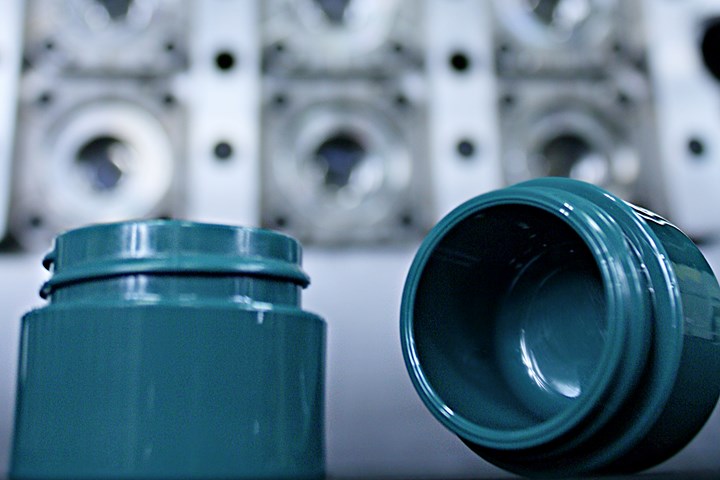
When you buy a mold, you’re not just buying steel—you’re buying parts that meet specified tolerances. (Images: Westminster Tool)
When you go to a moldmaker, what are you really buying—just steel or something more? The reality is you’re paying for the plastic part, and not just any part, but a dimensionally stable component that will meet the part print shot after shot for the millions of cycles that the tool will be running. With that in mind, why aren’t molders and moldmakers talking about plastic quality sooner?
Back in 2017, Westminster Tool implemented a more proactive plastic-quality design process. At that time, we looked at what we called our five “biggest losers.” These were projects that were our least successful in regard to timing, budget and part quality. We took a deep dive into all of them to find the root causes of the problems, and what we discovered was that in all five cases, the crux of the issue was plastic part quality—issues with tolerances and dimensions that we easily could have avoided in the beginning if we had just had the right discussions with our customers.


As a result of that deep dive, Westminster Tool now undertakes five steps on every project during design: Compare 2D prints to 3D models; CT scan existing parts if there are any; complete a dimensional risk analysis; understand Cpk goals; and perform a Moldex3D simulation. Once these steps are completed, we can define and align quality plans.
Why is it important to take these steps early in the process? Since Westminster Tool initiated this new protocol, we have found that one week added in the design phase—which is about how long it takes to complete these five steps—has eliminated at least three weeks on the back end in terms of troubleshooting, adjustments and more. In addition, the money and time expenditure to make an alteration to a mold design is far lower than having to make corrections to steel manufacturing.
2D to 3D Comparison
At the end of the day, the customer is paying for the plastic part’s dimensions and meeting the tolerances and quality requirements. To accomplish that, one of the first things Westminster Tool does during design is to take the 3D model and fully dimension and detail that model to ensure it matches the dimensions on the 2D part print. Since that print is what everything will be measured to, it is literally the definition of success. Putting this comparison into our process really helps us to identify any risk areas where the plastic dimension in the 3D model does not match the 2D expectation for that part.
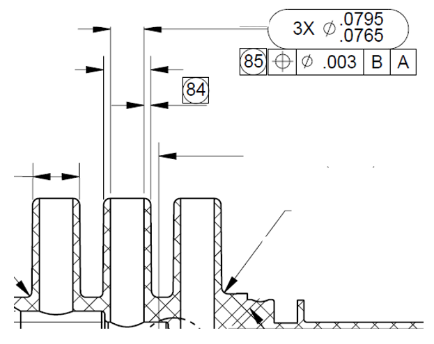
Take care to ensure that your 3D model matches the part’s 2D drawings.
Alerting to any discrepancies during the design phase greatly reduces lead times because 2D print changes typically require multiple approvals and can take upwards of two weeks. That’s not something you want to be waiting on at the end of the project during the inspection phase. In addition, thoroughly reviewing the part’s dimensions and tolerances also provides a fundamental understanding of its ultimate fit, form and function.
CT Scan Existing Parts
Any time Westminster Tool builds a mold for a customer that’s looking to boost production or to replace an existing mold for a current product (which we call a capacity tool), we send existing parts for a CT scan. Why? Because over the life of a tool many adjustments and changes can be made to the steel that are never noted or make it back to be noted in the original tool design.
So, if a customer comes to us and says, “Build us the same tool; we want it exactly how it is,” we know we can’t always assume that the files it provides us with are accurate and up to date. That can be caused by worker turnover or a lack of documentation, but ultimately many of the changes made to a mold over its life aren’t noted in the original tool design.
By CT scanning existing parts up front, we can build reality into our tool versus uncovering it the hard way during mold trials. With most capacity tools, those lessons have already been learned, and CT scanning the parts eliminates the time and cost of learning them all over again.
Dimensional Risk Analysis
This is an internally created worksheet that applies the SPI Standards and Practices of Plastics Molders. This document allows Westminster Tool to review dimensions, features and tolerances for a specific plastic and that material’s ability to meet those tolerances. Every resin has its own shrink and warp characteristics that are further influenced by part geometry. Because of this, every material can potentially achieve a different level of quality.
If we find a specification that’s tighter than the fine or standard tolerance, that flags us to a risk that this particular tolerance is not achievable in the plastic that’s been chosen, based on the design of the part. That doesn’t mean we’re going to try to soften or open the tolerance or say we’re not going to meet it. Instead, it starts a conversation about what mitigation plans can be put in place to make sure we meet the customer’s quality requirements. Those plans could involve anything from steel-safe dimensions to designing inserts in such a way that we’d be able to make modifications to them and still use them in the tool without a big impact on cost and time.
Cpk
Historically, if the tool builder isn’t performing mold validation or inspection services, Cpk (process capability index) isn’t something a customer would expect it to ask or worry about. Holding 50% of the print tolerance for our steel tolerance should ensure the steel is capable of holding that tolerance, cavity to cavity, over the life of the tool. However, when the customer wants a 1.33 Cpk or higher, that 50% of the plastic tolerance might not be good enough to ensure satisfying quality demands over the life of the tool.
For example, a 1.33 Cpk flags us to not only use 25% of the more narrow margin of plastic tolerance for that dimension—ensuring that we’re tighter than that 50%—but it also safeguards that the precision of the steel features we create are extremely accurate, eliminating one variable from all the variables in the injection molding process that could cause a dimension to be out of tolerance.
Bringing up Cpk requirements in the quoting phase ensures that Westminster can appropriately quote the tool. If the customer doesn’t have the information when we’re quoting, we automatically assume that there will be a Cpk requirement, and we build it in.
Moldex3D
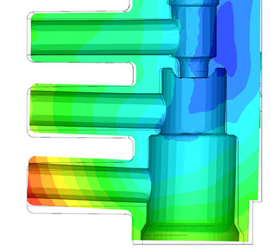
Westminster Tool uses Moldex3D flow simulation to compare what the molded part will actually look like to the 3D model, accounting for warprinkage and more.
Moldex3D is a flow-simulation and analysis software that allows Westminster Tool to look at the entire molding process. Utilizing this software not only allows us to design an effective and efficient tool, but it also helps us to understand the final molded part quality based on that injection mold design. This also ensures that any design choices or proposed changes are data driven and not just based on know-how or experience. Decisions around things like the size and location of gates, cooling channels and runners can be tested iteratively without cutting any steel.
Alignment of Quality Plans
Whether or not Westminster Tool is taking on inspection, we request the customer’s quality plan up front during the design phase. Typically, that quality plan includes the specific features and dimensions the customer is trying to hit, as well as the tolerances and preferred measurement method. Understanding measurement methods sets up Westminster Tool for success by informing us about how we’ll measure parts coming off the tool.
This could involve creating a fixture or designing a CMM program to take measurements, with the understanding that we’ll potentially need to buy equipment to measure the molded parts. Aligning these methods with the customer during the design phase reduces any chances of delays at the end of the project. Even when we are just performing a first-parts-off-tool trial and sampling parts internally, we’re able to inspect these first-off parts and make sure they’re meeting quality requirements right at the our own press. This reduces lead time involved in sending out parts for inspections, waiting for approval and then shipping the tool.
Defining Success First
At the end of the day, it’s really important to understand expectations in order for all of the parties involved to achieve success. It’s important that the OEM, contract manufacturer, tool builder and whoever else participates in the project are all on the same page about exactly what success looks like, because if our definitions differ then time and cost will catch up to us at some point.
Here are the questions you can ask if you have access to a part’s quality plan.
• What is your requirement for first-off-tool (FOT)?
• What is your requirement for mold factory acceptance test (MFAT)?
• Do you need to meet a Cpk? If so, how many shots are required for it?
• How are you going to perform Cpk inspection?
• Will there be any in-process checks required?
• Is there an acceptance plan that your mold builder needs to meet prior to shipment?
Remember to think about the end of the project at its beginning. That mindset will set you up for success by understanding from the start what the definition of success is and how you plan to measure it. Once we you have that definition, you need to consider any risks or obstacles that could keep you from achieving that definition of success. Finally, it’s important that all your entire team is willing to invest up front in order to minimize cost or time delays on the back end. For some companies, a major shift like this can seem daunting, but getting support and buy-in from all personnel involved is key. Shifting the conversation about quality requires full transparency and open communication, but the benefits far outweigh the challenges. Remember, one extra week up front can save at least three weeks on the back end, if not more.
ABOUT THE AUTHORS: Hillary Thomas joined the family business at Westminster Tool four years ago after several years of working as a global sales consultant. Her experience in leading corporate change through training programs has aided Westminster Tool’s philosophy of hiring for character and training for skill. Her experience in business development and customer relationship management aids in her current role as v.p. of Westminster Tool, where she now leads sales, engineering and marketing strategy.
Westminster Tool’s Hillary Thomas.
Seth Hale joined Westminster Tool in May 2017 after completing a Bachelor of Science in Plastics Engineering at UMass Lowell. In addition to designing injection molds for Westminster Tool, Seth now performs all Moldex3D analyses and supports process development and low-volume molding. Seth’s diverse technical experience has enabled the company to look at projects from a plastic capability viewpoint, helping his team become stronger partners in achieving challenging part tolerances.
Westminster Tool’s Seth Hale.


Related Content

Injection Molding Simulation Meets the Real World
Direct data interface between molding simulation and the injection machine links the computer model to the real-world process. This can improve results from product and mold design through ongoing production. A case study demonstrates these benefits for automotive components in a family mold.
Read More
50 Years of Headlines … Almost
I was lucky to get an early look at many of the past half-century’s exciting developments in plastics. Here’s a selection.
Read More
50 Years...600 Issues...and Still Counting
Matt Naitove marks his first half-century in plastics reporting, with a few of his favorite headlines.
Read More
How to Achieve Simulation Success, Part 2: Material Characterization
Depending on whether or not your chosen material is in the simulation database — and sometimes even if it is — analysts will have some important choices to make and factors to be aware of. Learn them here.
Read MoreRead Next

Westminster Tool Wins 2021 Leadtime Leader Award
The Plainfield, Conn. moldmaker earned the Moldmaking Technology magazine award, which has been bestowed since 2003 to toolmakers that go above and beyond fast lead times and excel in all aspects of the trade.
Read More
Westminster Tool Partners with Sumitomo (SHI) Demag
The Connecticut moldmaker added a new all-electric Sumitomo (SHI) Demag press, boosting its mold qualification capacity and giving the machine maker a New England outpost for sales and training.
Read More
Westminster Tool and Mantle Partner on 3D-Printed Mold Technology
The Connecticut mold maker will be one of two beta-testing sites for Mantle’s TrueShape metal 3D printer, with a medical device already borne out of an ongoing collaboration.
Read More