


Whether the fibers are long or short, incorporating glass or carbon reinforcements into thermoplastic matrices addresses the same fundamental objective—improving the mechanical and structural performance of polymers. These two primary methods of reinforcing injection molding thermoplastics differ in a number of ways, ranging from how they are combined with the polymer matrix to the level of performance they provide. End-use applications are another area where one form of fiber may be more appropriate than the other, but for molders, the main difference between short and long fiber is how aggressively they can be processed.
In Part 1 of this series, we address long-fiber processing fundamentals and best practices, including practical tips and guidance on maintaining fiber length and deriving maximum advantages for demanding end applications. For Part 2, we will provide the same information for short-fiber materials.


Preservation, Not Perfection
The primary goal in processing long-fiber reinforced thermoplastics is to preserve fiber length, which is critical to optimizing properties like strength and toughness. Fiber breakage negatively impacts polymer composite performance and may ultimately cancel out the benefits of using long fiber in the first place. Fiber breakage can be caused by careless handling, problematic tooling and part design, or the use of processing equipment or settings that have not been optimized.
The primary goal in processing long-fiber reinforced thermoplastics is to preserve fiber length.
Unlike short, chopped fibers, long fibers are typically produced using pultrusion. That process creates pellets by drawing a continuous roving of fiber and thermoplastic resin through a special impregnation die that enables the resin to encapsulate and bond with the fiber. The resulting strands are cut into pellets, typically 12-mm long, which feature unidirectional fiber reinforcements running their full length. This length is critical in enabling the polymer to transfer stress forces effectively to the stronger fiber.
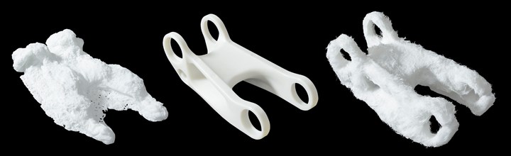
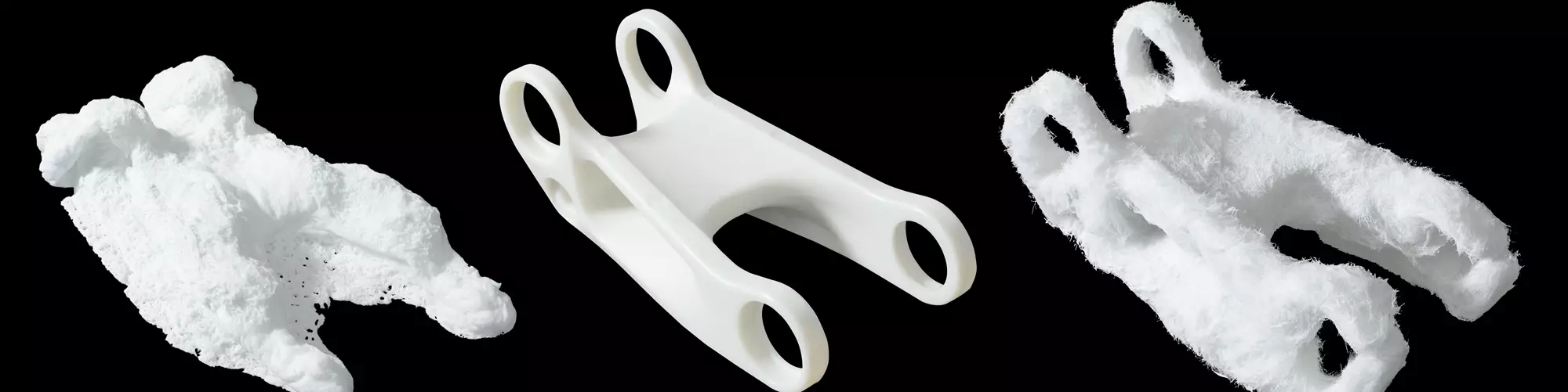
Left: Short-fiber internal fiber structure after resin removal. Middle: Injection molded part. Right: Long-fiber internal fiber structure.
When these pellets are used for injection molding, long fibers align and intertwine to form an internal skeletal framework that provides strength and toughness. Composites reinforced with long fibers, either glass or carbon, offer a high strength-to-weight ratio, toughness to resist impact, and cyclical fatigue endurance, as well as broader temperature resistance and better dimensional stability than short-fiber filled materials.
These durable materials deliver impressive structural performance that can compete with metals, while offering much lower weight than metal and utilizing the processing speed and efficiency advantages of injection molding. Carbon-fiber composites are especially valuable as metal replacements, because they are 70% lighter than steel and 40% lighter than aluminum.
Long-fiber reinforced composites can be used in very demanding automotive, sporting goods, aerospace, consumer goods and industrial equipment. Typical base resins include polyamide (PA, or nylon), polypropylene (PP), rigid thermoplastic polyurethane (ETPU) and high-temperature resins such as polyetheretherketone (PEEK), polyphthalamide (PPA) and polyetherimide (PEI). Although any thermoplastic can be reinforced with fiber, some deliver higher performance because they accept reinforcement better. More specifically, semi-crystalline resins accept fiber reinforcement better than amorphous resins, which means they get a higher boost in stiffness and strength.
Twice as much venting of gases is needed for long-fiber composites as for unreinforced materials.
Loadings (also referenced as weight percentages) of long-glass fiber can be as high as 60% (50% for long carbon fiber) before the fiber overwhelms the polymer matrix and leads to property degradation. These levels hold true for PP, PA and ETPU, but some high-temperature resins have a lower limit for fiber content due to moldability issues.
Processing Considerations with Long Fibers
Compared to unmodified or particulate- and powder-filled resins, molding long-fiber reinforced composites requires some accommodations to tooling, gating, molding equipment and part design. Processing for these materials also differs somewhat from that of short-fiber reinforced polymers.
As mentioned previously, preserving the length of the fiber is critical to success. Factors that can reduce fiber length include high pressures and shear forces from the injection screw, which are exacerbated by sharp angles and corners in the mold and runner system. With the goal of maintaining fiber length top of mind, here are three main processing considerations.
• Tooling Material and Design: Although long fibers cause less tool wear than short fibers—because there are fewer pointed fiber ends to impact the mold—the same types of tool steel can be used for both long- and short-fiber reinforced polymers. The most common type is P20 mold steel, which can last for more than 100,000 shots. If higher durability is needed (over 100,000 cycles), H13 chromium-molybdenum steel or A9 air-hardening steel are good options. In general, hardened tooling is best for fiber-reinforced thermoplastics. Worn tools can be refurbished with plating technologies. If short-run prototypes must be molded to prove out a design, even aluminum tooling can be used.
The mold design should avoid gates with small diameters that introduce shear, which can break the fibers. Because of the higher viscosity of fiber-reinforced resins, it is recommended to employ wide, fan-style gates or full-round gates instead of pin gates. Using a full-round runner eliminates dead-flow zones, which are areas where a solidified layer of plastic prevents full volume of flow. Also, any type of runner other than a full-round configuration has sharp corners that can increase shear and damage to the fibers.
Twice as much venting of gases is needed for long-fiber composites as for unreinforced materials. To provide this additional venting, larger openings can be used. These openings are not a problem, because the higher viscosity of long-fiber materials prevents them from flashing as readily as unreinforced resins.
• Molding Equipment: Standard injection molding equipment can be used for long-fiber reinforced thermoplastics, with some non-permanent modifications to protect the fibers’ length and accommodate higher viscosity. A low-compression or general-purpose screw with a free-flow tip and check ring is recommended. A general-purpose nozzle can be used, but nylon tips should be avoided because their hourglass shape (designed to prevent drool) can restrict flow, causing shear that leads to fiber attrition. Another recommendation for minimizing shear is to avoid reverse-taper nozzle designs. In general, a larger nozzle orifice—minimum of 7/32 in. or 5.6 mm—will ease the passage of viscous fiber-reinforced resins.
Carbon-fiber composites may require slightly more heat to achieve flow rates similar to those of glass-fiber composites.
A good rule of thumb for any injection molding machine is to use only 60% to 70% of shot capacity. Using too much capacity extends recovery time, while using too little means the material sits in the barrel for a longer period and can degrade.
• Processing Conditions: Before we discuss processing guidelines, it is important to address two issues: warpage and creep. Typically, long-fiber reinforced thermoplastic parts exhibit less warpage than short-fiber materials because the longer filaments’ entwinement reduces differential shrinkage. However, injection molded long-fiber parts can still warp. One reason is that fiber alignment in the flow direction, while enhancing part strength, can lead to anisotropic properties. To combat warpage, use alternative gate locations or part designs that avoid excessive fiber alignment in areas where high strength to carry structural loads is not required.
Like warpage, creep deformation tends to be less of a problem with long-fiber composites than with short-fiber compounds because longer fibers help dissipate load over a wider area of the part. A strong bond between filaments of long fibers allows the polymer matrix to transfer stresses to the stronger fiber, reducing creep. This is because fiber, analogous to a skeletal structure, does not flex or slide like polymer chains do. Resistance to creep is also a function of the higher aspect ratio (length to width) of long fibers. Higher aspect ratios allow the polymer to “grab onto” more fiber surface area.
The following are recommendations for processing long-fiber reinforced composites. Keep in mind that carbon-fiber materials tend to be more viscous than glass-fiber materials at the same weight percentage because carbon fiber is lighter and occupies greater volume. Carbon-fiber composites may require slightly more heat to achieve flow rates similar to those of glass-fiber composites. Factors to consider include:
• Drying—Long-fiber composite pellets should be dried using a desiccant dryer with a dewpoint setting of -40 C (-40 F). (Note: Even non-hygroscopic resins could have surface moisture). Consult the supplier’s recommended drying time and temperature for each resin type.
• Conveying—Pneumatic systems with filters are preferred to catch any loose fiber and prevent it from entering the molding process in clumps that could clog feeding systems or introduce defects into molded parts. The conveying line should avoid sharp corners and angles that can damage the pellets and cause loose fiber to be released.
• Molding—Melting long-fiber reinforced polymer pellets typically requires more heat and less dependence on screw shear (using a flat or reverse temperature profile for the molding machine barrel). Backpressure should be minimized to avoid excessive shear, and screw speed should be slowed down to avoid introducing solid, unmelted material that could damage the fibers. Another risk is using regrind containing broken fibers, which can affect material properties and performance. Incorporating regrind should be minimized or avoided. Long-fiber regrind is, in essence, short-fiber material because the fiber length has been degraded.
The mold should be filled between 95% and 99% during the injection phase and the remainder during the packing phase. This is because the high viscosity of long-fiber composites makes it difficult to fill a larger percentage during packing, which is done at less than peak fill pressure. The mold should be packed until the nozzle freezes off.
• Injection Speed and Pressure—In general, speeds slower than 25.4 mm/sec (1 in./sec) are ideal for minimizing shear and fiber breakage, although any speed less than 3 in./sec should suffice. On the other hand, filling too slowly can result in premature freeze-off of gates or other areas of thin-wall parts, causing a short shot.
Specific injection speeds will depend heavily on material viscosity. A material with less fiber content, say 30%, will flow better and could use a faster injection speed of 2-3 in./sec. A material with 50% fiber content will be more viscous and require a slower speed in the 1-2 in./sec range. For this reason, processing conditions recommended by the material supplier always give ranges, which should be adapted to particular situations. It is best to start in the middle of any provided range and then move one way or the other within the range, depending on what kind of results you are seeing. Although the goal of any processor is to achieve the shortest possible cycle times, if materials are processed in a way that degrades them (breaks the fibers), parts might not meet intended performance specifications.
Part Design
The part’s design should protect and maintain fiber length and promote fiber alignment, which occurs in the direction of material flow, to optimize strength and toughness. Strive for uniform wall thickness and avoid very thick areas—greater than 12.7 mm (½ in.)—so fibers will align in the flow direction. Random fiber orientation or balling formations result in reduced structural strength.
Fiber-reinforced materials are not like metals, so making a part thicker does not always directly translate into increased strength.
The minimum recommended wall thickness is 1.524 mm (0.06 in.) and the optimum wall thickness to promote fiber alignment is 3.175 mm (0.125 in.). Fiber alignment starts to decrease above 5.08 mm (0.2 in.). The maximum thickness is 12.7 mm or half an inch. Fiber-reinforced materials are not like metals, so making a part thicker does not always directly translate into increased strength. As the part becomes thicker, the fiber will not align throughout the full thickness.
Avoid designs with very long and flat flow lengths without reinforcing ribbing structures, because they are more likely to experience warpage. Also, the high viscosity of long-fiber composites can result in freeze-off of the material when it must fill a very long part.
Careful placement of weld lines or knit lines is important to avoid loss of mechanical properties that can occur when flow fronts simply meet each other without cross-over or intermingling of the fiber to create a structural bridge. Such weld lines are weak spots that lack the added strength and toughness of the fiber and rely solely on the performance of the matrix resin. For this reason, weld lines should be located away from critical structural areas.
Retaining the Benefits of Long Fibers
Successfully molding long-fiber reinforced composites requires some modifications to the design guidelines and processing parameters that work for unreinforced resins and short-fiber compounds. To derive the full value of long-fiber reinforced materials, which command a cost premium over unfilled and short-fiber grades for their higher performance, it is essential to follow best practices throughout processing. If long fibers break or do not align due to incorrect handling, mold design or equipment settings, their benefits of high strength and toughness will be reduced or even negated. The tips and recommendations presented in this article can help avoid issues and increase the likelihood of producing a strong, impact-resistant and dimensionally stable part.
ABOUT THE AUTHOR: Gordy Nagle, molding manager for long-fiber technologies at Avient, has more than 30 years of hands-on experience in processing thermoplastic composites. He has served as the molding manager at Avient’s application development center for long-fiber technologies in Winona, Minn., for the last 10 years. Nagle regularly visits customer sites to share best practices for processing long-fiber composites.


Related Content

How to Get Rid of Bubbles in Injection Molding
First find out if they are the result of trapped gas or a vacuum void. Then follow these steps to get rid of them.
Read More
Best Methods of Molding Undercuts
Producing plastics parts with undercuts presents distinct challenges for molders.
Read More
Improve The Cooling Performance Of Your Molds
Need to figure out your mold-cooling energy requirements for the various polymers you run? What about sizing cooling circuits so they provide adequate cooling capacity? Learn the tricks of the trade here.
Read MoreRead Next

Long Carbon Fiber Reinforced Composites Gain Interest
PlastiComp, for one, has added production capability to meet increasing demand.
Read More
Injection Molding: Better Flow Simulation with Fiber Reinforcements
Long and short fibers align during flow in the mold, and this, in turn, influences the flow pattern. New math helps Moldex3D simulate this phenomenon.
Read More