
The New Dimension in Mold Simulation
Keep an eye on the increasing prominence of so-called “3D” mold analysis. Two vendors of simulation software from Europe and Asia think it’s the best solution for a big proportion of injection molded parts. Established U.S. suppliers aren’t so sure. In any case, the capabilities of both 3D and standard 2.5D simulation are expanding rapidly.


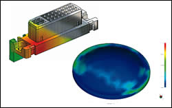
For thick parts like this manifold, 3D simulation gives a more accurate depiction of warpage (below) and fiber orientation (right) than conventional 2.5D programs. These simulations were made with Moldex3D software from EPS FloTek.
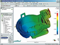
Molding a thin-wall connector with large thickness variations and tiny features such as pinholes is a headache to simulate in 2.5D. Parts like these are fueling the use of 3D simulation—in this case, MoldFlow’s MPI/3D.
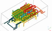
More accurate layout of cooling lines is obtained by direct integration with the CAD model using the faSolid 3D simulation from Plastics & Computer.
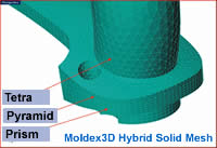
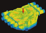
Use of various 3D element geometries to form a single model is a unique feature from Moldex3D. It lets you put more mesh elements in detail areas and requires fewer elements to cover large flat geometries in order to simulate accurately in less time.
North American molders now have a wider choice of software tools for predicting injection molding flow, cooling, fiber orientation, shrinkage, and warpage of thick parts. The past few years have seen pioneering developments in the newer branch of 3D flow simulation, tailored for thick and complex parts, as well as in conventional 2.5D midplane analysis that’s suited to thin-shell parts. Software vendors long established in North America, such as Moldflow Corp. and Plastics & Computer, have brought out new modules and enhancements for both kinds of analysis. They do not at present appear more committed to one type or the other. But they have new competition from imports such as Moldex3D from Taiwan and Sigmasoft from Germany, which are focusing almost exclusively on the 3D sector of the market in North America.
3D analysis is being applied for the first time to coinjection, multi-shot molding, and gas-assist, as well as to family tools and stack molds. New software analyzes fiber orientation and warpage in 3D. “3D technology is important here, since 2.5D can only show fiber in a plane, while 3D can show the orientation in different angles,” says Torsten Kruse, president of Kruse Analysis, which represents Sigmasoft. Other new 3D software reportedly does a better job than 2.5D in calculating the effects of cooling lines, mold inserts, or cavity metal composition.


Meanwhile, 2.5D software, still by far the dominant simulation technology, recently was enhanced to model microcellular foaming (Trexel’s MuCell process) and variable-orifice valve gating (Synventive’s Dynamic Feed). And simplified, low-cost versions of 2.5D analysis have now been beefed up with cooling and warpage analysis.
Why 3D?
Suppliers cite several reasons for the increased interest in 3D simulation. “In the last five years, many companies have been developing parts that are pushing the limits of design,” says Richard Carobus, president of EPS FloTek, the U.S. distributor of Moldex3D. These parts also strain the capabilities of older simulation software, he says. “2.5D simulation is a tried-and-true technology that has been around for 20 years. However, it does not work well on the thick sections of bulky parts, and it is also extremely difficult to model complex thin geometries. We run analyses with our 3D simulation on parts ranging from screwdriver handles to small connectors,” Carobus says. “Lately, we’re seeing the majority of plastic parts being analyzed with 3D solid elements.”
“Implementation of 3D simulation is just starting to happen,” says Kruse. “Many companies are designing their parts in 3D CAD, and we are looking for a corresponding jump in the use of 3D for simulation and analysis.”
More powerful computers are now able to generate models and solve analyses more quickly than ever before. This is especially critical for 3D simulation, as the solid elements are more “information-heavy” than the elements used in a 2.5D simulation. “Today’s dual-processor PCs can trim model generation and solution times by 40% to 60%,” says Carobus. A similar leap in performance is anticipated as more powerful 64-bit processors replace the current 32-bit chips.
Applying massive computer power to complex simulations has become more cost-effective with the emergence of multi-processor Linux-based servers that can share tasks with PCs. “With the addition of Moldex3D’s Linux Cluster capability, solve times will no longer be an issue,” says Carobus. “The PC is strictly for building models and viewing results; the Linux system is for the number crunching.” He claims such a set-up can quickly handle a model having millions of mesh elements, so 3D solution times will approach those for 2.5D simulation.
Shell or solid modeling?
The decision to use conventional 2.5D software or the newer 3D type depends on the geometry of the part, its complexity, as well as the material, and the sort of simulation data the user wants, says Giorgio Bertacchi, president of Plastics &Computer. There is general agreement that traditional 2.5D midplane modeling is best suited for thin-shell parts that require fairly short analysis times. Parts with a high level of complexity and thick walls or wide variations in wall thickness are better suited to 3D analysis, though longer modeling time will result.
However, the type of molding process—such as gas assist, coinjection, overmolding or a stack or family mold—can also influence the choice, because today specialized modules for these processes exist mainly in 2.5D, though 3D versions are in the works or just emerging in the marketplace.
On the other side of the coin, 3D analysis offers some types of information that 2.5D cannot match—such as identifying turbulent vs. laminar flow, as well as jetting, bubbles in the melt, and the effects of gravity. 3D simulation can also provide more insight into the condition of the mold itself. “In 2.5D, if you have an insert, you put a mesh on it then try to calculate how the heat travels through that volume. But in 3D simulation you can see the heat lines—isothermal variations—when you cut through the model,” says Kruse.
While some applications are squarely in the province of 2.5D simulation, more parts can now be run in 3D. “If you are meshing an automotive body panel that is 3 ft long x 4 ft wide and 0.100 in. thick, it would be impractical to do in 3D with standard tetrahedral or voxel elements because too many of them wold be required,” says Carobus. “This is a midplane type of part. However, with Moldex3D’s new hybrid prismatic mesh, this part can now be analyzed with 3D elements,” he adds. This unique hybrid mesh, which can combine different sizes and shapes of 3D elements in the same model, drastically reduces the number of elements necessary for such a part.
For relatively simple parts, 3D simulation cannot match the short analysis times with 2.5D simulation. Suppliers such as Moldflow have created products such as MPI/Fusion that allow users to analyze 3D solid CAD models directly, without first creating a midplane manually. “But there is always a compromise when going from a 3D CAD solid model of the part to a midplane model for analysis,” says Carobus. “There is no program that can automatically create an accurate midplane for all part geometries, so many midplanes have to be extracted by hand. For certain complex part geometries, the human mind must make critical decisions as to the best way to represent the midplane.”
Meet the newcomers
The Moldex3D family of software for Windows and Linux includes both 2.5D “Shell” and new 3D “Solid” versions. Moldex3D was developed by CoreTech System Co. Ltd. in Taiwan, based on research begun at the National Tsing Hua University. CoreTech has sold over 400 user “seats” for its technology, most of them in Asia. It introduced the software worldwide in an English-language version in 1999. The firm exhibited at last year’s NPE show in Chicago. “More than 1300 case studies have been published to validate the accuracy of the software,” says Carobus.
In North America, EPS FloTek is promoting only the 3D Solid version. Moldex3D software features a novel hybrid solid-element meshing approach that reportedly delivers more accurate modeling with greater mesh density and fewer elements than competitive models. Users can mix and match different 3D elements, including tetrahedral, voxel, prismatic, pyramid, and hexahedral. “If you have a thin area you can use a prism mesh, which will give you several elements through the thickness. When a thicker section of the same part is being modeled, the software can transition automatically into larger, volume-based voxel or tetrahedral elements,” says Carobus.
Using different elements reportedly gives finer mesh contours than if a single element type were used throughout. Additionally, the “Auto Runner Mesh” function allows users to generate a solid-element-based runner system with one mouse click, while simultaneously optimizing the mesh density near the gate.
An advanced interface with structural-analysis programs was recently added to the program suite, which includes modules for meshing, filling, packing, cooling, warpage, fiber orientation, gas-assist, and RIM molding. The recently released 7.0 version features a larger materials database (more than the previous library of 5700 grades), improved FastPack and FastCool solvers, and multi-CPU capability. The ability to simulate coinjection, overmolding, and two-shot molding will be available in version 7.1 later this year, along with a Linux-cluster version.
Moldex3D developers are currently testing a new warpage module. The feature exports a “negative” of the warped part as an STL model. This model can then be imported into CAM software, which allows tool builders to accurately cut the “windage,” or “negative” of the warp, into the steel.
CoreTech also offers a module that runs as a plug-in within the popular SolidWorks CAD package. Moldex3D Works provides 3D solid-element filling simulation only.
Sigmasoft of Aachen, Germany, is 100% committed to 3D simulation. Its Sigmasoft software was commercialized in 1998 but only reached U.S. shores in the past couple of years.
Designed for Windows or Linux, it has a fully automated meshing program that reportedly works in 30 sec to 2 min. Sigmasoft also integrates the mold model with any tool inserts and cooling channels. One result is said to be a more accurate view of heat transfer in the mold.
One of the software’s unique abilities is modeling what happens to the part after it leaves the mold. It calculates the progressive evolution of part warpage and stresses at any time from demolding until the part reaches ambient temperature. Whereas some software programs may predict the total warpage after demolding, Sigmasoft models the part’s behavior for up to 6000 sec after demolding, says Kruse. For insert-molded parts, the software takes into account the inserts, including their metallic composition, to calculate stresses and warpage.
The software can also calculate the air pressure in the mold during filling to determine the best locations for venting. This is useful since compression of air in the mold can cause burn marks or “dieseling,” especially with thermosets or other materials that exhibit outgassing.
Sigmasoft also has a multi-cycle analysis feature that runs multiple iterations of the mold-temperature calculation to arrive at the steady-state temperature of the mold. “That is a degree more accurate than just assuming a mold temperature,” says Kruse. This feature can help identify heat build-up in the tooling cycle by cycle. Users can monitor the simulation to optimize operating cycle times.
Sigmasoft is developing a 3D multi-phase analysis that can handle two materials in the mold, such as gas and resin, or coinjected melts. The next-generation Sigmasoft 4.3 version is expected to have dual-processor capability for Windows that may speed up analysis by 30% to 40%.
The company offers an “evaluation seat” for $1000 (not including training) and a yearly lease for $39,000. The software can be purchased for $77,000.
Gas-assist goes 3D
Thick parts using gas-assist can for the first time be modeled and analyzed accurately in 3D using new simulation software developed in the U.K. Cinpres Gas Injection offers a service to model such parts using software developed at the Centre for Polymer Processing Simulation and Design in the School of Engineering of the University of Wales in Swansea. The software was developed in a three-year joint project with CGI. The simulation can show filling of the mold with plastic followed by the introduction and exhaustion of the gas in the mold and cooling, says Dr. John F.T. Pittman, co-director of the center at the university. The software uses solid elements (tetrahedral or hexahedral) to model various gas-assist methods—short-shot, overflow, and push-back.
CGI claims this is the only software today that’s capable of detailed modeling of the interaction between the molten polymer in the center of the part and the incoming gas. “We solve the problem of the flow of the polymer and the gas by tracking the interface between them,” says Pittman.
What sets the software apart from midplane analyses, which provide information only on the fraction of the part cross-section occupied by gas, is that it shows details of plastic wall-thickness variations around the circumference of the gas channel, especially in bends. Its particular value is in the analysis of thick-walled tubular parts such as handles for auto parts and housewares. The software is said to accurately model potential processing problems with gas-assist, such as fingering, blow-out, or blow-through, and it accounts for effects of a gas delay, where the plastic partially cools before gas injection.
The software reportedly can create the mesh in minutes from a suitable CAD model and can analyze a medium-size model (200,000 elements) in one day—including plastic filling and primary and secondary gas penetration. Results can be exported in the form of a CAD model of the hollow plastic part, suitable for stress analysis, says Pittman.
More news in 3D & 2.5D
There’s also news from the established simulation suppliers in North America. Moldflow has developed several new modules for the latest MPI 4.1 version of its Moldflow Plastics Insight analysis package. The new modules include one for MPI 3D that predicts fiber orientation, warpage, and thermal-mechanical property distribution in thick parts.
Moldflow has also extended its thermoset modeling capability to its 3D software. MPI 4.1 now can analyze hot runners in 3D. In addition, MPI 3D can display a plot of injection pressure and clamp force versus time. MPI 4.1 supports 64-bit computers, which allow very large models to run more quickly.
Within the last year, Moldflow enhanced its 2.5D software with modules to simulate the MuCell microcellular foam process from Trexel, the Dynamic Feed sequential valve-gating system from Synventive (with up to 32 independent pressure profiles at different nozzles), and both two-shot and insert overmolding processes. Previously, analysis of the first and second shots required two separate simulations that could not be integrated, so it was not possible to model interactions between the two materials at the interface, says Peter Rucinski, director of product marketing.
Warpage prediction and analysis of cooling efficiency are two new features recently added to the Moldflow Plastics Advisers (MPA) software, a simplified package designed for quick, low-cost assessments early in part and mold development. The new Performance Adviser and Cooling Circuit Adviser modules are part of the latest MPA 7.0 release. These functions were previously offered only on higher-end MPI products.
Several new capabilities for 2.5D and 3D analysis packages are also available from Plastics & Computer. One of these is multi-shot simulation of filling, packing, and holding for its faBest 2.5D software, the result of a four-year collaboration with the Fiat Research Center in Italy. Plastics & Computer also introduced the ability to model family and stack tools with its midplane software. It’s worth noting that Plastics & Computer has long used a proprietary hybrid modeling approach that combines 2.5D midplane filling analysis with 3D solid cooling simulation.
The firm’s 3D faSolid module has a faster solver that cuts analysis time to only about twice that of its 2.5D faBest module. “We’ve developed a modeling and analysis strategy that considers the planning, work flow, and organizational needs of molders and moldmakers,” says Giorgio Bertacchi. “This benefits moldmakers facing just-in-time deliveries. This process can provide several iterations of 3D analysis to optimize a design in under a week.”
Sequential valve-gating analysis was extended to faSolid two years ago. But so far, the most elaborate work in sequential modeling has been done with 2.5D faBest. Bertacchi feels he widened the envelope in that field when he modeled a 6-ft-long part produced with 11 valve-gate nozzles.
Simulate the runners
Simulating just the runner system instead of the cavity is the focus of software developments from Mold CAE Solutions, a three-year-old firm. The firm’s MoldCAE Specialist is a fast and easy-to-use flow-analysis program that helps to optimize hot or cold runners. The program is intended for mold makers and mold designers rather than OEM part designers, says president Bob Meng. “So many people talk about simulation of the mold cavity and optimizing the cavity, but the final say over the cavity design lies with the customer, not the mold designer or mold maker. What these tooling experts can really optimize is the delivery system of the melt to the cavity. They can change the layout and the gate size and balance the system for uniform pressure and filling.” It can be especially useful for solving filling problems with asymmetrical cavity layouts. The system is priced at $4500. It can simulate family and stack molds. The newest version 4.2 can handle larger models, including 144-cavity PET preform molds.
MoldCAE Specialist software doesn’t require a CAD model, nor does it need to be meshed, so it has neither 2.5D nor 3D elements. Users can follow a simple tutorial to learn to run a simulation within 30 min. Users enter data about the type of runner system, runner diameters, runner layout, gate type, number and position of gates, the plastic material, and injection-pressure capacity of the machine. The simulation runs in a few seconds. Users can add or remove gates, change their size or position, and modify other simulation data with a few keystrokes. Users can also add a simplified cavity design to the model to get a better indication of required filling pressure.
MoldCAE specialist calculates maximum injection pressure and a detailed distribution of pressure and temperature in the runners and cavities. It also shows shear rate, shear stress, and shear heating in the runner system. It also shows melt velocity throughout the system, clamp-force requirements, cooling times, and short shots. The program offers suggestions about runner and gating design, optimal number of cavities, and processing parameters.
A database of commonly used thermoplastics comes with the system. Users can add new materials to the library. They can also set up a library of typical gates, runner types, and runner layouts.


Related Content

Compact Hybrid Injection Molding Machine Launched
Sumitomo Heavy Industries Ltd. (SHI) has introduced the iM18E, promising the smallest footprint in 20-ton machines.
Read More
IPEX Opens Injection Molding Facility in North Carolina
The pipe and fittings manufacturer’s new 200,000-square-foot facility represents a $200 million investment and will create 150 jobs.
Read More
Injection Compression Molding as Alternative to Thermoforming
Arburg will show its all-electric Allrounder 720 A press utilizing injection compression molding to create thin-wall IML cups from PP.
Read More
Fakuma 2023: More Details on New Machine Line
Wittmann Battenfeld has released more details on the new EcoPower B8X debuting at Fakuma (October 17-21; Friedrichshafen, Germany), which it previously announced.
Read MoreRead Next

How Polymer Melts in Single-Screw Extruders
Understanding how polymer melts in a single-screw extruder could help you optimize your screw design to eliminate defect-causing solid polymer fragments.
Read More
Advanced Recycling: Beyond Pyrolysis
Consumer-product brand owners increasingly see advanced chemical recycling as a necessary complement to mechanical recycling if they are to meet ambitious goals for a circular economy in the next decade. Dozens of technology providers are developing new technologies to overcome the limitations of existing pyrolysis methods and to commercialize various alternative approaches to chemical recycling of plastics.
Read More