
Tips and Techniques: Mold Filling Analysis Now You Can Adapt Injection Mold Filling Simulation for MuCell
While mold-filling simulation is a very common tool for predicting the fill patterns of an injection mold, in our judgment there is not yet a commercially available, satisfactory filling simulation for microcellular foam molding.
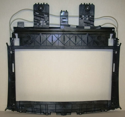
Fig. 1—Conventional mold-filling software modified for the MuCell process enabled this prototype automotive sunroof opening frame to beat the estimated cycle time, eliminate flash, and meet all OEM quality specs with minimal mold modifications after the first parts were tested.
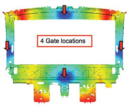
Fig. 2—Initial mold-filling simulation revealed an unbalanced fill pattern on a mold designed with four valve gates (red arrows), resulting in some areas between gates filling much sooner than others.
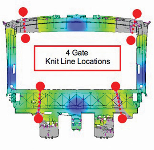
Fig. 3—Another issue with the four-gate design was that knit lines ended on or near mounting holes, causing a weak area at a highly stressed point.
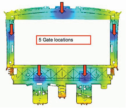
Fig. 4—Development of a five-gate model eliminated many of the problems uncovered in the four-gate version. Fill pressures decreased to about 8000 psi and weld lines between the gates all tended to come together at the same time, reducing overpack areas that would limit foaming.
While mold-filling simulation is a very common tool for predicting the fill patterns of an injection mold, in our judgment there is not yet a commercially available, satisfactory filling simulation for microcellular foam molding. Trexel has seen a need for this process with the growing range of applications of its MuCell microcellular foam molding process—especially in more complex, structural parts for automotive and other durable-goods markets. (See sidebar for an explanation of the MuCell process.) Recently, Trexel engineers developed a methodology and techniques for using the standard mold-filling simulations to predict fill patterns and estimate weight reductions. As a result, it is now possible to adapt the standard mold-filling simulation programs to provide useful guidance when designing a mold for the MuCell process.
Please be aware that the MuCell-adapted simulation procedure described below concerns only the filling characteristics and does not involve other aspects of these software packages, such as cooling and warpage predictions.


MODIFIED SIMULATION PROCEDURE
Here are the basic modifications for simulating the MuCell process with standard mold-filling software:
- Identify a grade of material that is similar (same filler level and chemical composition) to that being used for the part but with a 12% to 15% lower viscosity. This accounts for the reduction in viscosity that occurs with the MuCell process.
- Pick an injection speed that will match what is expected for the MuCell application. Keep in mind that the injection velocity for the MuCell process may be 25% to 50% faster than for injecting solid parts. Profiling the injection velocity at the start of fill is common for sub-gates to prevent heavy surface splay around the gates.
- Decrease hold pressure to 25% of the injection pressure.
- Lower the pack and hold time to 2 sec. While the actual process will typically use a pack and hold time closer to 0.5 to 1 sec, it has been observed that some simulation packages give poor results if the time is set below 2 sec.
- Size the gates 30% to 50% larger than usual. The faster injection velocity can lead to shear-induced blisters and surface imperfections around the gates. Increased gate size minimizes this effect. However, this recommendation may not be appropriate for sub-gates as it may prevent proper degating in the mold.
- Material and mold temperatures should be set as expected for the process.
EVALUATING THE RESULTS
When running a mold-filling simulation for the MuCell process, the goal is to determine the types of conditions that can limit weight reduction in the part, and then remove them. The most common issues are high flow-length/wall-thickness ratio, unbalanced fill, gas traps, and lack of appropriate venting. We have seen many instances where an unbalanced flow or a blind pocket standoff forced the use of higher-than-desired injection pressure to completely fill the part. Consequently, a part that would have easily achieved a 10% weight reduction was now limited to only 4% because of a small oversight in the mold-filling simulation that could have easily and inexpensively been corrected if it was caught in the design phase.
When evaluating the results of the fill simulation, consider the following:
- Balanced fill pattern. An unbalanced fill pattern will limit the obtainable weight reduction. There should be two to four areas of the mold that are not filled until just before the end of the simulation. These areas should be weld lines between gates or at end of the part, and not backflow areas. Backflow conditions must be eliminated to achieve maximum benefits of the MuCell process. It is usually necessary to run multiple simulations with adjustments to gates or through the addition of flow leaders to achieve the best results.
- Location of weld lines. Identify all weld lines in the simulation and determine the ability to vent these areas. If venting is not feasible, it will be necessary to rerun the simulation with adjustments to the gate locations and/or number of gates. Add flow leaders to the model to move the location of the weld lines to an area that can be vented.
- Look for “racetracking” or blind pockets that can seal off perimeter vents, resulting in gas traps and non-fills. These types of gas traps are the most common restrictor of weight reduction and can frequently result in weight reductions of less than 3%.
- Check small standoffs or blind pockets for complete fill. Pay particular attention to standoffs at or near the end of fill. Sharp corners in blind pockets should be avoided.
- Maximum melt pressure to fill the cavity should be less than 8000 psi. Experience has shown that weight reductions of 8% to 10% can be achieved at 8000 psi or lower pressure to fill the mold cavity. Injection pressure will increase as the flow-length to wall-thickness ratio increases or material viscosity increases. Pressures of 8000 to 10,000 psi usually result in weight reductions of only 5% to 8%. Pressures of 10,000 to 12,000 psi usually result in weight reductions of 3% to 6%
CASE HISTORY: LARGE AUTO PART
We put these principles to the test on the Inalfa sunroof frame for the Cadillac CTS (Fig. 1). Inalfa’s goals for this project from the customer were well defined: 1) very tight dimensional tolerances; 2) flatness, which is critical to the fit and smooth movement of the sunroof glass and sunroof shade; 3) proper knit-line locations to maintain structural integrity; and 4) maintaining proper alignment and preventing damage to the hollow overmolded tubes.
The goals of the molder were threefold: 1) minimize the cost and complexity of the hot-runner system; 2) determine the optimal gate number and locations to eliminate the need for valve-gate sequencing during injection; and 3) keep mold iterations as few as possible to meet tight timing on first approved parts and achieve all of the customer goals.
Trexel’s objectives were: 1) keep the fill pressures low to allow for proper MuCell expansion and benefits; 2) balance the mold filling and keep the polymer fill pattern uniform; 3) keep the part thickness uniform to facilitate faster cycle times; and 4) eliminate any possible gas traps by adjusting the fill pattern before steel was cut.
Taking into consideration each of these requirements, the first step was for all the teams involved to review the preliminary part design for issues related to tooling, part thickness, and moldability. Once the preliminary design was close, the CAD files were sent out to have flow analysis run on a four-gate design. Initial flow data on the four-gate design showed three major problems.
The first was that the pressures to fill would exceed 10,000 psi polymer pressure, too high to achieve adequate density reduction. This is particularly critical for reducing orientation of glass fibers. The second was an unbalanced fill pattern that resulted in some areas of the mold between gates filling much sooner than others, as can be seen in Fig. 2. The third was the issue of the location of the knit lines (Fig. 3) ending on or near mounting holes, causing a weak area at a highly stressed point.
When the five-gate model (Fig. 4) was developed, many of the problems that were seen in the four-gate version were eliminated. The fill pressures decreased to about 8000 psi and the weld lines between the gates all tended to come together at the same time, reducing overpack areas that would limit foaming. The team determined that the modest additions in cost and complexity for the hot runner system for the five-gate design were well offset by the benefits.
After the first shots off the tool were measured, the part was far closer to meeting the print than expected, and the tooling required few changes. Cycles were less than the molder quoted, while the parts still met or exceeded the customer’s quality standards. The lower injection pressure of the optimized MuCell design delivered the added benefit of eliminating flash around all the metal inserts.
Work has not been done to validate the cooling and warpage components of the simulation software. Standard cooling recommendations for the MuCell process should be used.
About the Authors
Levi Kishbaugh is v.p. engineering for Trexel Inc., Woburn, Mass. Scott Powers is the technical development manager in Rockford, Mich. Trexel is an employee-owned company specializing in development and commercialization of microcellular foamed processes for plastics. Contact: (781) 932-0202 • trexel.com.


Related Content

Injection Molding Simulation Meets the Real World
Direct data interface between molding simulation and the injection machine links the computer model to the real-world process. This can improve results from product and mold design through ongoing production. A case study demonstrates these benefits for automotive components in a family mold.
Read More
50 Years of Headlines … Almost
I was lucky to get an early look at many of the past half-century’s exciting developments in plastics. Here’s a selection.
Read More
Take Time to Save Time: Five Steps in Mold Design to Reduce Back-End Troubleshooting
Westminster Tool shares how the one week it typically takes to perform these five steps in the design phase can save three weeks or more in an overall tool build.
Read More
How to Achieve Simulation Success, Part 2: Material Characterization
Depending on whether or not your chosen material is in the simulation database — and sometimes even if it is — analysts will have some important choices to make and factors to be aware of. Learn them here.
Read MoreRead Next

Rigid Packaging Goes Lighter, Thinner With Microcellular Foam
Molding higher volumes of a rigid thin-wall part typically means going to a larger press for increased injection and clamping capacity.
Read More
New Light on How to Optimize Properties of Microcellular Foams
With the growing popularity of thermoplastic microcellular foams (such as those produced by the MuCell process of Trexel Inc.) comes increased need to understand how to optimize foam properties through appropriate foam structure.
Read More
3D Molding Simulation Growing in Accuracy & Capabilities
New developments in 3D simulation can handle processes like gas assist, coinjection, and multi-shot molding and add features like birefringence prediction.
Read More