
Tooling: Clamp Pressure & Cavity Land Area, Part 2
What you need to know to prevent flashing and mold damage.

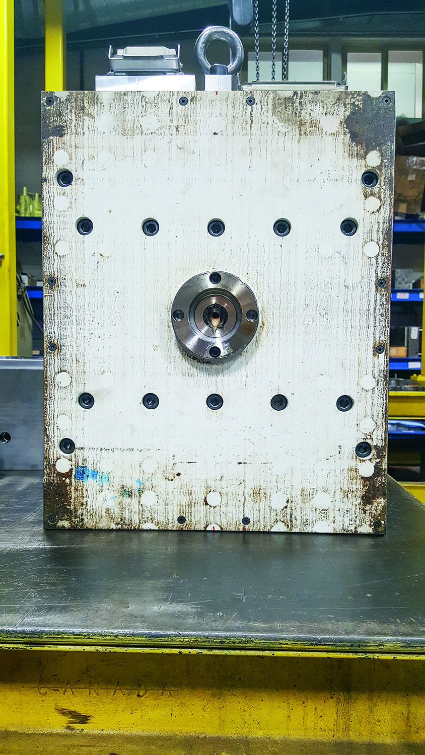
The rust marks on just the corners of this insulator plate suggest the molding machine’s stationary platen is concave from wear.
Platen wrap can cause the corners of a mold to create indentations.
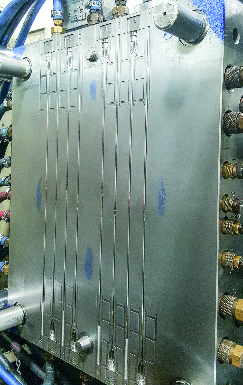
A high-volume hot-runner mold with both sides cut directly into pre-hardened plates.
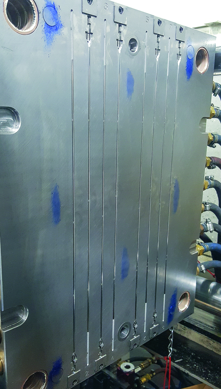
A high-volume hot-runner mold with both sides cut directly into pre-hardened plates.


If you are having problems with flash, then blue off the mold. If the blue indicates that there is significantly more contact at the corners of the mold, or the corners of the cavity inserts, and not much around the perimeter of the cavity, then you have a problem.
But is the problem due to the mold, the machine, or the mold in the machine?


Since mold bases are typically two to three times harder than the soft cast-iron platens of a molding machine, the platens will wear over time. It stands to reason that the older the machine, the greater the amount of wear. And that wear will be predominantly in the center, resulting in a platen that is somewhat concave. This condition won’t be very evident on small molds in large machines, but it can cause flash to form on the inner edges of a part and runner on larger molds, due to a lack of support in the center.
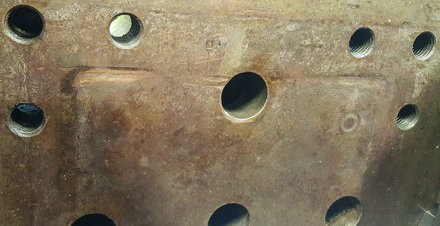
Core inserts should protrude slightly beyond the surface of the plate in which they are mounted.
You can overcome this problem by adding shim around a flanged locating ring, or by pre-loading the center support pillars. But on the next run, when the mold is hung in the original smaller machine, you may develop flash on the outer edges of the part and accelerate wear in the center of the platen. To solve the root cause of the problem and prevent this condition with all your molds, the worn platen should be removed and machined flat.
If you are a custom injection molder, you’re probably flipping molds several times a day. To satisfy customer delivery requirements, smaller molds are often put in larger presses due to machine availability at that time. If the width and length of these molds are less than roughly 70% of the distance between the tiebars, they can be subjected to a condition known as “platen wrap.” When the machine is clamped under high pressure, the platens literally wrap around the mold and cause the corners of the mold to hit harder than it does in the center. If you have any dents in your platens that look like the corners of a mold dug in, they probably did. This can result in the part flashing on the inner edges as well as the runner, which are the same results you might see with a large mold mounted on a concave platen.
It’s possible that the stack-up tolerance of all the mold plates causes one corner, or one side of a mold to be thicker than the others. This would cause the platen to squeeze the mold unevenly and can also cause a mold to flash. But unless some grievous error was made during mold construction, this is not a very common occurrence.
Want to learn more about tooling? Read more at our Know How Tooling Zone.
The more likely cause, other than a concave platen or platen wrap, is the mold design itself. If the cavities are machined directly into the cavity plate instead of into individual inserts mounted in pockets, or mounted on the face of the cavity plate, this is called “cut in a solid.” The same machining configuration can also be employed on the core side, but this is usually only done on prototype, bridge, pre-production, or other low-volume molds, to save time and money. Since there are exceptions to almost every rule, depending on the geometry of the part, you will occasionally come across a high-volume mold with both sides cut in a solid.
Core inserts should protrude slightly beyond the surface of the plate they are mounted in. The same is true for stripper-ring inserts in a stripper-plate mold. This is called being “proud.” Some moldmakers like the inserts to protrude about 0.002 in. to 0.005 in. Others like to go as much as 0.020 in. to 0.030 in. There are pros and cons to both preferences. I prefer just a few thousandths proud. The important thing is that the inserts are above the surface of the plate. If they don’t protrude at all, the parting-line shutoff area becomes the entire surface of the plate, minus the area of the cavity and runner, and that can cause a problem.
If neither core nor cavity are proud, I suggest relieving a triangular area, with a base leg of 2 to 4 in., at each corner of the parting line by just 0.002 to 0.004 in. This guarantees the corners of the mold will not hit first if a platen-wrap condition exists. This small amount of relief also helps prevent potential damage to critical shutoff areas caused by anything that can make the mold rock, such as accidently closing on a molded part.
Conversely, if the core or cavity are proud by more than 0.005 in., adding safety pads in the corners of the mold with the same 0.002 to 0.004 in. of clearance can be a smart precautionary measure. This is particularly important for single-cavity or offset molds where the cavity may be machined in the lower half of the mold, and nothing is machined in the upper half.
Now let’s talk about pressure. If a 200-lb man steps on your foot with the front half of his shoe, it’s going to hurt. If a 100-lb woman, half the weight of the man, steps on your foot with the small end of her high heeled shoe, you’re going to have a broken toe. It all comes down to pressure. Pressure is equal to the force divided by the area. When it comes to injection molding, the force is equal to the tonnage of the molding machine. That’s a fixed value.
If your parts are flashing, you probably think it’s because the machine is too small and doesn't have enough clamp force. But before you go hanging the mold in a larger press, blue off the mold and look at where that force is being applied and how much total area is involved.
There is a bit of a balancing act regarding where a mold should shut off and by how much. You typically don’t want to shut off over the entire face of the mold. This will only make the problems associated with platen wrap or platen concavity that much worse. Nor do you want the force localized or concentrated on a specific area where it may exceed the fatigue strength of the steel. (Note: Yield-strength values of steel are based a non-cyclic or single constant load. Fatigue strength, or endurance limit, is where the number of cycles to failure is infinite. Fatigue strength is roughly 10% to 20% of a material’s yield strength.)
All molds must have what’s called a “land” or shutoff area around the sprue bushing, runner and perimeter of the cavity. If they don’t, the material will squirt out and create flash. For good reason, the land area around the cavity is often referred to as the “cavity seal.” The width of this land must be enough to prevent excessive compressive loading and prevent the fragile vents from collapsing. The total land area of the mold is equal to the total area of the cavity seal, plus all the other areas or faces that contact with one another when the mold is closed.
Except for conical and bar-type interlocks, which need to be slightly preloaded in order to be effective, it is extremely important that all of the other contact or shutoff areas hit almost exactly at the same time. A low-pressure alignment study is perfect for verifying whether they do or not. (See Part 1 of this column in last month’s issue.) If they don’t shut off at the same time, the areas that hit first will be subjected to the highest compressive force, and potentially exceed their fatigue strength.
Since the plastic pressure inside a mold continually decreases as the melt travels along the flow path from the machine nozzle tip all the way to the end of fill, the highest pressures are in the sprue, runner and gates—and those are where you need a significant amount of land. It is for this reason that I don’t recommend adding any vents near a gate. They reduce the land area in this critical location and are usually ineffective there, anyway.
Since the fatigue strength of steel is appreciably less when the surface is rough or has a notch-sensitive stress riser, a good rule of thumb is not to have any more than 3.5 tons/in.2 of pressure on materials having a hardness value of 300 Brinell (32 Rockwell C), or any more than 5 tons/in.2 on materials having a hardness value of 50 Rockwell C. Any more pressure than that can cause the material to exceed its fatigue strength and collapse over time.
Let’s run some numbers as an example. We know pressure (lb/in.2) = force (lb)/area (in.2). So if a 100-ton (or 200,000-lb) machine clamps on an 8.5-by -8.5-in. core insert mounted proud in the B-plate, and the opposing A-Plate cavity depression is 7 by 7 in., the pressure on the resulting 3/4.-in.-wide land area around the cavity is equal to:
200,000/((8.5 X 8.5) – (7 X 7)) = 8602 psi or 4.3 tons/in.2
That is perfectly acceptable for a heat-treated cavity and core, but not acceptable if either one of the two mating components is pre-hard. In a case like this, you need to add some load-carrying or load-bearing pads to increase the total land area and absorb some of the force, because in this example, the total land area is insufficient and the vents are subject to collapsing over time.
Now for the bad news: Bluing off a mold only solves half the mystery. It tells you where the steel is hitting when the mold is clamped, but not whether the support within the mold is sufficient to resist the injection pressure of the molten plastic. If you put a magnetic dial indicator on the parting line, you can easily determine whether the mold is opening due to insufficient clamp force and how much injection pressure it takes to do so. But if the indicator doesn't budge, or if the flash is thicker than the indicator reading, the mold may be collapsing internally.
There are a number of potential causes for this: insufficient number of support pillars; support pillars that are too small in diameter and are sinking into (coining) their adjoining plates; one or more of the plates is too thin and is flexing; or insufficient steel supporting the back of the cavity or core inserts. For hot-runner molds, there may not be enough manifold support. Any one of these conditions can cause a part to flash regardless of the tonnage of the molding machine.
It’s common to get a small amount of flash opposite a sprue bushing subjected to very high injection pressure, especially at very high injection velocities. Preloading the center support pillar 0.001 to 0.003 in. will usually solve this insufficient support problem. If you have to use 0.003 in. or more of preload in the center of the mold, use progressively smaller amounts on the adjoining pillars until you get to the rails. This is referred to as crowning the mold, like the arch on many flatbed tractor trailers. But you should really look for the root cause of why you need so much shim. Increasing the thickness of the B-Retainer plate might be a better option. As a side note, I don’t recommend ever using AISI 1030, DIN 1.1178, or # 1 medium carbon steel for mold bases. Some brands aren’t even on the Rockwell C hardness scale and can be the root cause of some of the problems I just mentioned.
I am not a big fan of doing things twice. When sampling a mold, I like to use a machine I know will have sufficient clamp force. Once the process is established, the tonnage is reduced until there is a dimensional or aesthetic issue, such as flash. From there, I add a safety factor—usually 20%, to give me the ideal machine size for that particular mold.
A word of caution: If a mold typically runs in a certain size machine, but only a larger machine is available the next time it is scheduled to run, make sure the clamp tonnage is set to the lower tonnage of the smaller machine. If you get burns, shorts or high gloss on the outer edges of the parts, you may have just crushed the vents. If you get sticking in the cavity and can feel a small lip or burr of steel on the inside perimeter with your finger nail or a sharp pencil—you just rolled over the edge of the cavity seal. What will really make you pull your hair out is when the texture on the sides of the part begins to abrade and scuff, or the parts begin to stick in the cavity, but you don’t see or feel anything in the mold. Excessive tonnage can cause the side walls of a cavity to collapse, thereby reducing the draft angle. Neglecting to use the proper tonnage can cause extensive—if not catastrophic—damage to both the mold and the machine. If you don’t have a system or procedure in place to ensure the proper tonnage is used, you should consider adding a large placard on the outside of the mold.
ABOUT THE AUTHOR: Jim Fattori is a third-generation injection molder with more than 40 years of molding experience. He is the founder of Injection Mold Consulting LLC, and is also a project engineer for a large, multi-plant molder in New Jersey. Contact jim@injectionmoldconsulting.com; injectionmoldconsulting.com.


Related Content

How to Select the Right Tool Steel for Mold Cavities
With cavity steel or alloy selection there are many variables that can dictate the best option.
Read More
Hot Runners: A View from the Bottom Up
Addressing hot-runner benefits, improvements, and everyday issues from the perspective of decades of experience with probably every brand on the market. Part 1 of 2.
Read More
How to Optimize Pack & Hold Times for Hot-Runner & Valve-Gated Molds
Applying a scientific method to what is typically a trial-and-error process. Part 2 of 2.
Read More
Why Shoulder Bolts Are Too Important to Ignore (Part 1)
These humble but essential fasteners used in injection molds are known by various names and used for a number of purposes.
Read MoreRead Next

Tooling: Clamp Pressure and Cavity Land Area
What you need to know to prevent flashing and mold damage.
Read More
Processor Turns to AI to Help Keep Machines Humming
At captive processor McConkey, a new generation of artificial intelligence models, highlighted by ChatGPT, is helping it wade through the shortage of skilled labor and keep its production lines churning out good parts.
Read More
Advanced Recycling: Beyond Pyrolysis
Consumer-product brand owners increasingly see advanced chemical recycling as a necessary complement to mechanical recycling if they are to meet ambitious goals for a circular economy in the next decade. Dozens of technology providers are developing new technologies to overcome the limitations of existing pyrolysis methods and to commercialize various alternative approaches to chemical recycling of plastics.
Read More