
TOOLING: Dealing with Lifters--Part 2
This installment delves into more detail on some variables of design and fitting/timing of the lifters, which can cause issues or failures during molding.
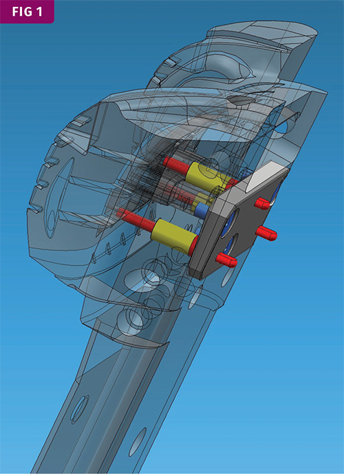
Detail shows a lifter that has push pins to prevent the part from sticking to the lifter detail. The pins are in red and springs are in yellow.
Detail shows a lifter that has decelerated travel. When the ejector is all the way forward, the lifter will be lower than the rest of the ejector.


Lifters at times can cause read-through and gloss problems, due to lack of cooling, deflection (as mentioned last month), and the lifter not being flush with the cavity surface. It typically is desirable to have the lifter rest 0.002-0.003 in. below the cavity surface to prevent drawing or sticking issues.
When there are any rib details in the lifter and the cavity that the lifter travels against, the rib detail in the lifter should be wider by 0.001-0.002 in. to reduce dragging and sticking issues when traveling against the rib detail in the cavity.


If the lifter is “proud” with sharp edges, it can peel up plastic, leaving flakes in the tool that will create defects in the next part. In some cases, a slight texture on the lifter surface can camouflage read-through.
Lifter pre-load is also a critical spec, also referred to as timing the lifter. This is established by the moldmaker. Pre-load is what ensures the lifter is held down all the way during the molding process. If the lifter is built to the exact length, plastic pressure on the lifter cavity details can pull the lifter up, causing flash, dimensional issues, or read-through.
The lifter is typically attached to the ejector plates with a slide and gibs. These components have some clearance to allow for mechanical movement. In most cases, the lifter rod or shank will be shortened by 0.002-0.003 in. to accommodate these clearances and make sure the lifter is down tight during mold close. In one case where I refurbished a mold with new lifters, the parts produced had a clip detail that was out of spec by 0.007 in. I knew I had the lifters properly positioned before sampling the mold, as was verified on subsequent examination. The lifters were on a 7° angle but had too much unsupported length. The plastic pressure was deflecting the lifter shank and pushing the lifter down during the injection process. In this case, we raised the lifter, the opposite of pre-load, to compensate. Not the greatest solution, but redesigning the mold was not really an option.
I have seen this issue on other molds. If the lifter or detail is below the cavity surface, this is something to consider. The only way it can be pushed down, if timed properly and verified, is from cavity pressure causing deflection on the lifter shank. Making sure the lifter has minimum unsupported length with a bearing surface, guides, bushings, or a buddy/helper pin are potential solutions.
If the lifter has shutoff surfaces on the top (where the stationary half has details that shut off on the top of the lifter), pre-load is not as critical. But too much pre-load can also create maintenance issues. I have seen many tools over the years where too much pre-load has caused broken lifter bolts and held the ejector plates forward. In a few cases the lifter pre-load varied by 0.005-0.020 in., contributing to tooling issues. This is solely the responsibility of the moldmaker and its process for timing lifters. There are various ways to time lifters and adjust pre-load; they all work, but close attention to detail is needed by the moldmaker to make sure the outcome is correct.
Spotting and fitting the lifters is also critical for the moldmaker. For lifters with heads and drafted sidewalls, the fit should not be too tight, to avoid stressing the lifter bolts trying to pull the lifter home. After the lifter is fitted, you should be able to push the lifter all the way down and out of the pocket by hand and not a hit from a tool. If it requires a hit to the bottom of the pocket to get the lifter out, the fit is too tight. On lifters with square shanks, I will chamfer the four corners below the cavity surface to provide clearance. I have seen many cases where the corners were not cleared enough and contributed to galling.
One other misconception is that pre-hardened H-13 lifters (40 RC) do not need further hardening. The old standard of 10 points of RC difference for wear surfaces has been proven wrong on the lower RC scale. When running lifters at 40 RC against P-20 steel, which is 28-30 RC, galling will occur at some point. On the higher RC scale, above 50 RC, spreads can be less than 5 RC. I have had tools running millions of cycles with the cavities in S7 steel at 50-52 RC and the lifters at 52-54 RC with no lifter failures.
P-20 or pre-hardened H-13 steel can be good base materials for lifters, but always nitride or Dyna-Blue them to prevent galling. Coatings can also work but are not as durable for the long term. When using copper alloys like MoldMax, AMPCO, or Moldstar for increased thermal conductivity, coatings are not a necessity but can improve wear. The exception is when running glass-filled materials: Copper-alloy tooling should always be coated to prevent erosion from the glass fibers.
Round lifter rods are maintenance friendly, but it is critical to key the rod to prevent rotation and damage to the lifter and cavity. Typically a nitrided ejector pin will be used because the center is soft enough to drill and tap. Square lifter shanks are also commonly used, but repair work is a little more involved. Typically, if a square lifter is bent or broken, we cut the rod where it would be positioned in the bearing surface and splice a new shank with a notch, which is then bolted and dowled. Whether the lifter is hardened steel or a copper alloy, we use P-20 material for the splice and then have it nitrided.
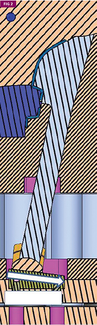
The lifter slide (in the ejector plates) should move freely by hand, with no dragging, to reduce the chances of failure or wear. This is especially true in cases where the lifter is decelerated or accelerated, which adds more friction. Deceleration or acceleration is used when the lifter detail or undercut in the part is on an angle and not parallel with the parting line. This means the lifter will need to travel at angle more or less than the ejector stroke to pull on the angle of the part detail. The lifter slide will be machined on an angle, so that as the ejector travels forward, the lifter will either be above the ejection with an accelerated slide or below it with a decelerated slide (see Fig. 2).
One other consideration in the tool design is trying to hold the part in position without sticking to a lifter. One common method I use is to add ring detail on ejector pins to hold the part in position and prevent the part form traveling with or sticking to the lifter.
Also, with some flexible materials such as PP, it is sometimes necessary to have an ejector pin or straight lifter bar going up the sidewall of the part to prevent the part from flexing and sticking to the lifter. And in a few cases, push pins can be used on the lifter detail to assist in releasing the part from the lifter (see Fig. 1).
ABOUT THE AUTHOR: RANDY KERKSTRA
Randy Kerkstra has been in the plastics industry for more than 26 years, occupied frequently with troubleshooting injection molding. He is currently a tooling manager for a large, multi-plant molding and manufacturing company.
Contact: kbmoldingsolutions@gmail.com.


Related Content

How to Start a Hot-Runner Mold That Has No Tip Insulators
Here's a method to assist with efficient dark-to-light color changes on hot-runner systems that are hot-tipped.
Read More
How to Optimize Pack & Hold Times for Hot-Runner & Valve-Gated Molds
Applying a scientific method to what is typically a trial-and-error process. Part 2 of 2.
Read More
Why Shoulder Bolts Are Too Important to Ignore (Part 2)
Follow these tips and tricks for a better design.
Read More
What You Need to Know About Leader Pins and Bushings
There’s a lot more to these humble but essential mold components than you might suspect. Following the author’s tips could save much time, money and frustration.
Read MoreRead Next

Why (and What) You Need to Dry
Other than polyolefins, almost every other polymer exhibits some level of polarity and therefore can absorb a certain amount of moisture from the atmosphere. Here’s a look at some of these materials, and what needs to be done to dry them.
Read More
People 4.0 – How to Get Buy-In from Your Staff for Industry 4.0 Systems
Implementing a production monitoring system as the foundation of a ‘smart factory’ is about integrating people with new technology as much as it is about integrating machines and computers. Here are tips from a company that has gone through the process.
Read More
Lead the Conversation, Change the Conversation
Coverage of single-use plastics can be both misleading and demoralizing. Here are 10 tips for changing the perception of the plastics industry at your company and in your community.
Read More