
Tooling: Why Ejector Pins Break And How to Prevent It, Part 2
Here’s the when and how to reduce the unsupported length of pins.

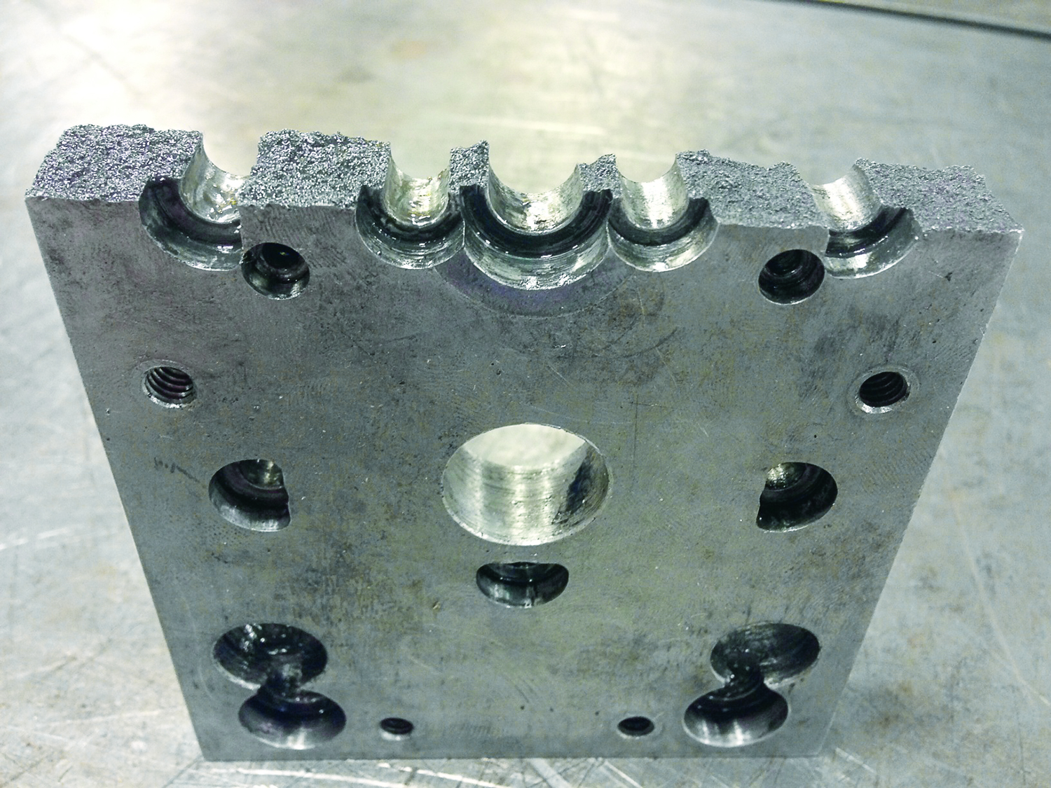
An ejector retainer plate can crack when subjected to an uneven load.
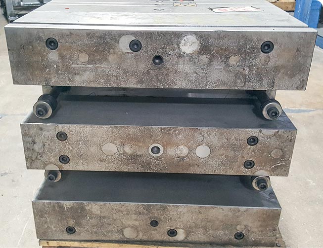
Spacer blocks on the back of a mold solve a minimum stack-height problem.
If you have to use ejection-stroke limiters, nylon or hard urethane are good material choices.
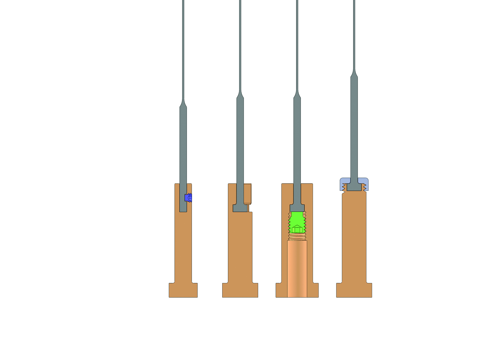
Cross-sections of various ways to make an ejector-pin extension.
There are several methods you can use to reduce the unsupported length of an ejector pin.


Let’s start with the basics and build on that. Ejector pins are mounted in the ejector retainer plate by means of a through hole for their body and a counter-bore for their head. The typical head-diameter tolerance of a standard ejector pin is +0.000 to -0.010 in. from nominal. The counter-bore diameter for the head of a pin in the retainer plate is typically 1/32-in. larger than nominal. The typical head-thickness tolerance for a standard ejector pin is +0.000 to -0.002 in. from nominal. The counter-bore depth for the head of a pin in the retainer plate is typically +0.001 to +0.003 in. deeper than nominal. Most pins have a 1/32-in. radius where the shaft of the pin meets the head, so clearance must be provided. Ejector-pin counter-bore sets, available through most molding supply companies, automatically add a chamfer to account for the radius on the pins.
The tolerance for the diameter of an ejector pin varies depending on the size, type and manufacturer. It can be as much as -0.0010 in. below nominal to as little as -0.0000 in. below nominal. Keep in mind, that’s a full thousandth. Most mold designers will make the through hole for the pin in the ejector retainer plate 1/64-in. larger than nominal. This allows a standardsize drill to be used and provides roughly no more than 0.008 in. per side of “float” in the event the through hole in the plate does not precisely align with the through hole in the core.


The ejector retainer plate can have holes for the ejector pins, ejector sleeves, core pins, guide bushings, return pins, support pillars, lifters, screws and various other component parts. Basically, these plates look like Swiss cheese. Last month I discussed the problems associated with uneven loads on the ejector system. Cracking a fragile ejector retainer plate in half is one of those problems.
An ejector pin’s unsupported length is a critical variable and a common cause of its bending, buckling and breaking. If you have ever watched an Olympic pole-vaulting event, you have seen how much the pole bends after the vaulter plants it in the box and leaps up to clear the bar. These poles can be over 16-ft long. If the vaulter holds the pole in the middle, instead of at the end, how much do you think that pole will bend? Obviously, not nearly as much.
The material, hardness, diameter and even the length of the pole did not change. Only its unsupported length changed. The unsupported length is equal to the distance between two fixed or pivoting points of an object. This same premise also applies to ejector pins.
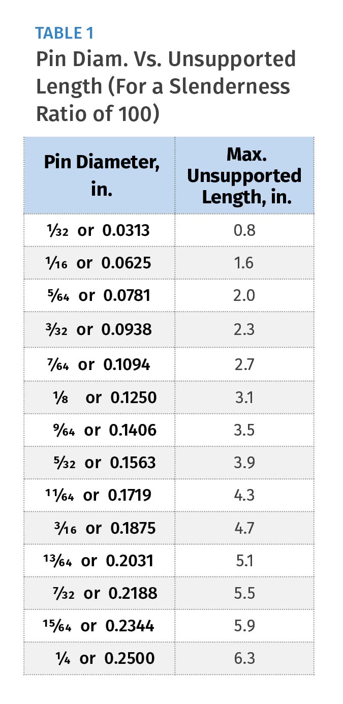
A Swiss mathematician and physicist by the name of Leonard Euler developed two formulas back in the mid-1700s that moldmakers can still use to predict whether an ejector pin will buckle and collapse. One formula is rather simple. It is called the Slenderness Ratio. This ratio is equal to the unsupported length of a slender column, such as an ejector pin, divided by the radius of gyration. Don’t get excited. The radius of gyration for an ejector pin is simply its diameter divided by four. So the formula is:
Slenderness Ratio = Unsupported Length ÷ Diameter ÷ 4
If the value of this ratio is greater than 100, you can expect the pin will fail due to buckling. Working backwards, I used a Slenderness Ratio value of 100 and solved for L, the maximum unsupported length of ejector pins of various diameters. Table 1 details the results for 1/32-in. through .-in. ejector pins.
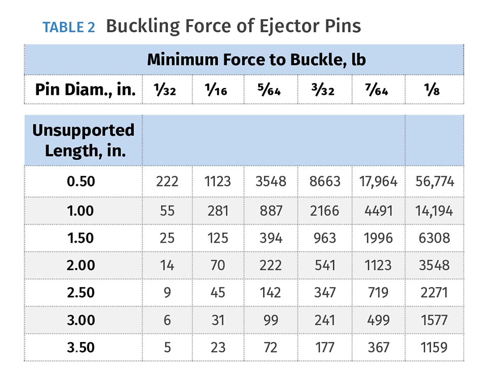
Euler developed another, much more involved formula, and I will spare you from going into too many details about it other than to say the formula allows you to calculate the amount of force a slender column, like an ejector pin, can withstand before it buckles. The formula is very useful in understanding how the unsupported length of a pin is directly related to the amount of force it can apply to eject a part before buckling.
For example, Table 2 shows that a 5/64-in. ejector pin, with an unsupported length of 3 in. can push a plastic part with 99 lb of force before it buckles. A pin with that same diameter and an unsupported length of 1.5 in. can push a part with 394 lb of force before it buckles. While that may be four times the amount of force, you need to be careful here. This quadruple relationship only occurs when you cut the unsupported length in half. If you reduce that same pin’s unsupported length by just 1/2 in., from 3 in. to 2.5 in., the force only increases by 43 lb, which is a factor of just 1.4 times. Regardless, are you beginning to see how important the unsupported length is?
If you think you might have an issue with an excessive amount of unsupported length in a mold, how do you reduce it? The first thing to do is estimate how much ejector stroke is needed to safely eject the part off the core. For a new mold, this can vary depending on the mold design, part geometry, material and other factors.
Typically, you add about a half an inch or so to the overall height of the part, but this all depends on ejection speed, undercuts, mold design, robotics and various other factors.
When you order (or design) a mold base, you specify what height you want the ejector-housing rails to be. That dimension is equal to the desired ejector stroke, plus the thickness of the ejector plates and the rest buttons. You shouldn’t want to go any longer than your estimation, and you obviously never want to go any shorter. If it turns out that the mold design does not have the minimum stack height required for the intended press, which is common for large flat parts, it is very easy and relatively inexpensive to add spacers to the back side of the ejection clamp plate to make up the difference. Adding a spacer plate to the molding machine’s platen, instead of spacers on the mold, is rarely a better alternative.
Let’s assume that when the mold goes into production, an ejector-pin buckling problem starts to develop. If the ejector stroke can be shortened, do not add stroke-limiting spacer blocks. They won’t help reduce the unsupported length of the ejector pins. You need to reduce the height of the rails and the length of all of the ejector and return pins by an equal amount. Ejector-stroke limiters are beneficial only if you don’t have a buckling problem, but you want to increase the longevity of the mold by preventing production personnel from overstroking the ejector plates. If you ever add ejector-stroke limiters, mount them in line with the machine’s ejector bars.
I cannot stress this enough. It is probably the most common cause of bent ejector plates. I like to make the stroke limiters out of a nylon or a hard urethane to help absorb the impact caused by momentum or an improper machine setting. As shown in Tables 1 and 2, the smaller the ejector-pin diameter, the shorter the unsupported length needs to be to prevent it from buckling. Any pin 7/64 in. or smaller should be stepped or shouldered to reduce the pin’s unsupported length. The shoulder on stepped pins is 1/8-in. diam., and is available in 1/2-, 2-, 3- and 4-in. lengths. You want the shoulder of the pin to enter the support plate when the ejector plate is back against the rest buttons. If a 4-in. shoulder is still not long enough to enter into the support plate, you can either have custom pins made or you might be able to use an ejector-pin extension.
Now here’s the weird thing: Several mold-component suppliers offer extensions for ejector sleeves, but no one that I know of offers extensions for ejector pins. Maybe someday they will realize this is something molders occasionally need. Until then, we will have to make our own extensions, and there are multiple ways of doing so, as shown in Fig. 1.
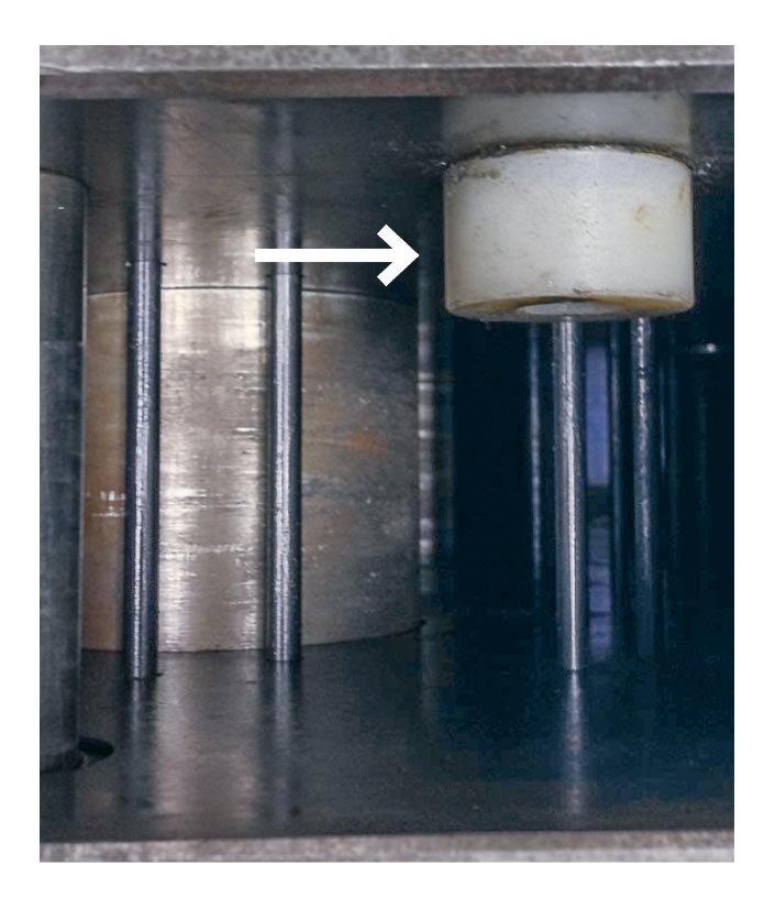
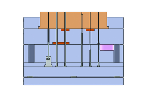
In Fig. 2, the ejector pin on the left is mounted in an ejector-pin extension, because the shoulder is too short to enter the back of the support plate. Other pins are depicted with bearing inserts on the bottom of the support plate, on the top of the support plate, and on both top and bottom of the support plate. These bearing inserts are a simple way to reduce an ejector pin’s unsupported length.
It is nearly impossible for an ejector pin to collapse due to high injection pressures.
They can be made of various types of metal—from bronze to heat-treated tool steel, whatever is your preference. The ejector pin on the right uses a thin-walled drill bushing, which I have found to be excellent for this application.
Here’s a test: Which ejector pin or pins in Fig. 1 still has/have a good chance of buckling due to excessive unsupported length?
Let’s revisit the practice of providing lateral float around an ejector pin in the ejector return plate. While it sounds like a practical idea to compensate for any misalignment, one study suggests that this added clearance actually promotes wear of the through hole in the core and reduces the force the pin can withstand before it buckles. If the through hole in the ejector retainer plate has significant clearance, the unsupported length increases by an amount equal to the length of the through hole.
For example, ejector retainer plates are usually 1/2 in.- or 5/8 in. thick. Small-diameter ejector pins have a head thickness of 1/8 in. Therefore, the unsupported length of the pin increases by 3/8 to 1/2 in. That can be a significant amount if the diameter of the ejector pin is 7/64 in. or less, but not much of a concern for pins larger than 1/8-in. diam.
As long as you adhere to the maximum unsupported length calculated using a Slenderness Ratio of 100, it is impossible for an ejector pin to collapse as a result of the material’s plastic pressure on the face of the pin.
Let me prove it:
Table 3 specifies the maximum unsupported length using a Slenderness Ratio of 100 for various size ejector pins—from 1/32 in. up to a full 1.0 in. It then shows how much force it takes for the pin to buckle at that unsupported length. Lastly, it shows how much force is applied to the face of the pins using a ridiculously high plastic pressure value of 40,000 psi. Every pin can withstand two or three times more than this excessive amount of pressure.
ABOUT THE AUTHOR: Jim Fattori is a third-generation injection molder with more than 40 years of molding experience. He is the founder of Injection Mold Consulting LLC, and is also a project engineer for a large, multi-plant molder in New Jersey. Contact jim@injectionmoldconsulting.com; injectionmoldconsulting.com.


Related Content

How to Set Barrel Zone Temps in Injection Molding
Start by picking a target melt temperature, and double-check data sheets for the resin supplier’s recommendations. Now for the rest...
Read More
The Effects of Temperature
The polymers we work with follow the same principles as the body: the hotter the environment becomes, the less performance we can expect.
Read More
Understanding Strain-Rate Sensitivity In Polymers
Material behavior is fundamentally determined by the equivalence of time and temperature. But that principle tends to be lost on processors and designers. Here’s some guidance.
Read More
Formulating LLDPE/LDPE Blends For Abuse–Resistant Blown Film
A new study shows how the type and amount of LDPE in blends with LLDPE affect the processing and strength/toughness properties of blown film. Data are shown for both LDPE-rich and LLDPE-rich blends.
Read MoreRead Next
Why (and What) You Need to Dry
Other than polyolefins, almost every other polymer exhibits some level of polarity and therefore can absorb a certain amount of moisture from the atmosphere. Here’s a look at some of these materials, and what needs to be done to dry them.
Read More
Understanding Melting in Single-Screw Extruders
You can better visualize the melting process by “flipping” the observation point so that the barrel appears to be turning clockwise around a stationary screw.
Read More
People 4.0 – How to Get Buy-In from Your Staff for Industry 4.0 Systems
Implementing a production monitoring system as the foundation of a ‘smart factory’ is about integrating people with new technology as much as it is about integrating machines and computers. Here are tips from a company that has gone through the process.
Read More