
Troubleshooting Material Burning In Hot-Runner Systems
Burns in hot runners can be misleading and hard to diagnose correctly. Follow these tips to track down the root cause of your problem.
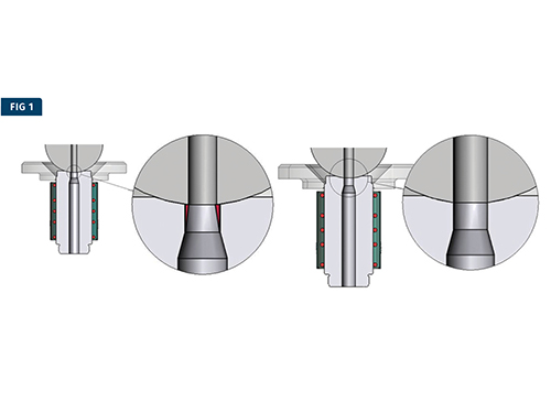
Left: Machine nozzle-tip orifice is smaller than the inlet orifice, creating an area of stagnant material at the wall of the inlet orifice. Right: Machine nozzle-tip orifice is the same size as the inlet orifice, eliminating any stagnant material at the wall of the inlet orifice
Left: Flow bore of sliding nozzle does not align with the flow bore in manifold at room temperature. This design relies on an assumed amount of thermal expansion of the manifold to move the flow bores into perfect alignment. Proper alignment is heavily dependent on operating temperature and machining tolerance of both the hot runner and the mold. Right: Flow bore of the threaded nozzle aligns perfectly with the flow bore in the manifold at room temperature. These nozzles are designed to flex as the manifold grows keeping the bores aligned at any temperature. Proper alignment is not impacted by temperature or machining tolerances.
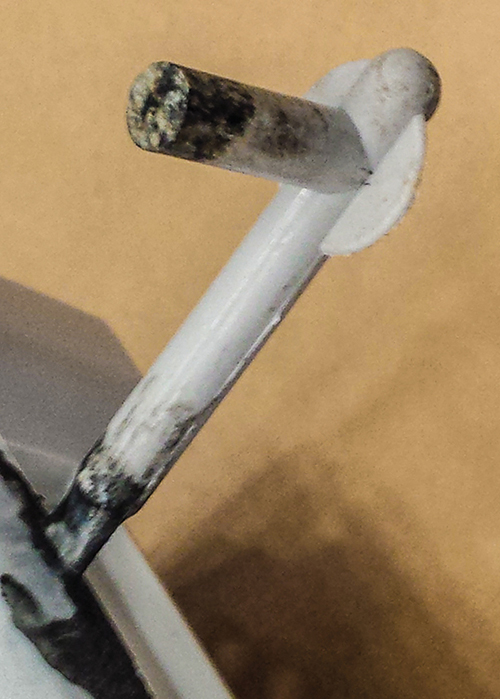
This burn may appear to be coming from the hot-runner nozzle but it is in fact the result of a gas trap caused by improper sequencing of the valve pins.


Hot-runner systems provide a variety of benefits: They save the molder money by eliminating wasted material and improving cycle time. They allow the part designer to place the gates in any location required to properly fill the cavity. Hot runners even allow the molder to open and close the valve gates independently for optimal cavity filling and locating of weld lines. But with all these benefits come an additional layer of complexity to the tool and increased residence time for the molten plastic, which can lead to material burning in the hot-runner system.
It is very common for the root cause of burns to be misdiagnosed, causing the molder to waste excessive time searching for a resolution to the problem, when a little extra time spent up front in understanding the issue would lead to a solution much quicker. Degradation of material in a hot-runner system is typically caused by excessive thermal history, hot spots, stagnation points, venting, or a combination of the four.


EXCESSIVE THERMAL HISTORY
When diagnosing a problem with burning, the complete heat history of the material must be considered. Many polymers are time/temperature sensitive, which means they can only withstand elevated temperatures for a limited amount of time. The higher the temperature, the less time until degradation begins. However, even time spent at lower temperatures adds to the heat history of the material and can contribute to degradation down the road.
A common false assumption is that if the material does not look burnt when purged out of the molding machine nozzle, then the problem must lie in the hot-runner system. Lack of burnt material in the purge does not mean the material has not already been subjected to an extensive heat history, giving it very little chance of making it through the hot runner without burning. Many materials will show no visible sign of degradation until they reach a tipping point, when burnt material begins to appear. Because the molten material flows through the hot-runner system last, the residence time in the hot runner is often just the “straw that breaks the camel’s back,” but it may appear to be the root cause of the burning.
Even material drying adds to the resin’s thermal history. Drastically overdrying the material typically won’t show any visible negative impact on the pellets but it does add to the polymer’s thermal history and can make the material more likely to burn later in the process.
Another common false assumption is that if the burn only shows up in the material coming out of certain hot-runner nozzles, then there must be something wrong with those nozzles. Which nozzles are feeding the burnt material is valuable information that can help determine where the root of the problem lies, but it can also be misleading.
Flow of the molten polymer through the hot-runner system is always laminar. Laminar flow simply means the material flows in parallel layers, so that there is no mixing between layers of the molten polymer. Material at the wall will stay at the wall and material in the center of the flow will stay at the center. Although the flow through a hot runner with multiple splits and turns is a bit more complicated, the material will always take the same path through the hot runner. Because of laminar flow, a burn originating upstream—in the machine nozzle, for example—will always follow the same path through the hot runner and often will appear in material coming out of certain nozzles.
HOT SPOTS
An obvious cause of burns in a hot-runner system is any area of the hot runner with a steel temperature over setpoint. Any hot-runner zones overshooting the temperature-control setpoint are obviously a potential issue. On the other hand, just because the temperature controller shows all the zones to be at setpoint doesn’t mean that is truly the case. The only way to be sure that accurate values are being reported by the controller is to remove the top clamp plate and check the hot-runner steel with a pyrometer while the system is at setpoint.
Sometimes it will be assumed that there is a temperature issue in a particular hot-runner nozzle because it is feeding an area of the part where a burn appears, and that turning down the heat to the suspect nozzle will immediately solve the problem. Turning down the temperature of the nozzle feeding the area where a burn exists is logical but is often only a temporary solution. If a burn is originating from a problem upstream, and because of laminar flow it is following the wall of the flow bores to a certain nozzle, then cooling that nozzle will cool the material at the flow-bore wall first.
This can slow the movement of material near the flow-bore wall or even freeze it in place if the temperature is lowered enough, essentially trapping the already burnt material in place, which can temporarily eliminate the burn from the part. By doing this, the root issue has not been resolved, so the burn will eventually make its way back into the part.
STAGNATION POINTS
Stagnation points are spots in the hot runner where material becomes trapped, rather than flowing through. This causes a small amount of material to see an extreme thermal history, degrading and slowly bleeding into the flow of the moving material on each shot. Suppliers of high-quality hot runners pay a great deal of attention to potential stagnation points during manufacturing and inspection of the systems they build. Even in a perfectly constructed hot-runner system, there are a couple of common stagnation points.
The most common of these is at the interface between the machine nozzle and hot-runner inlet. The inlet commonly has an orifice smaller than the inlet flow bore. This is done to reduce the amount of material that drools out of the inlet when the hot runner is heated and the machine nozzle is pulled away from the inlet. The molder should size the orifice of the machine nozzle to match that of the hot-runner inlet. This is frequently not done, either by oversight or a misunderstanding of what the relationship between the orifices should be (see Fig. 1).
When molding with a cold runner, the machine-nozzle orifice should be slightly smaller than the orifice of the cold sprue bushing to be sure material freezing on the machine-nozzle side of the interface does not hold the sprue in the mold when it opens. The material at this interface gets ejected with the cold runner on every cycle, so a stagnation point is not a concern.
But with a hot runner, there is no reason to make the machine nozzle orifice undersized; a line-to-line fit is ideal, eliminating any potential stagnation point. It is also important that the barrel and machine nozzle be perfectly aligned to the inlet.
Another common stagnation point can be at the interface of the hot-runner nozzle with the manifold. Hot-runner nozzles fall into two categories with respect to how they mate to the manifold—sliding and threaded. Sliding nozzles are not physically attached to the hot-runner manifold. They are installed in the mold first and then the manifold is placed on top of them, held down either by bolts or just by pads touching off on the top clamp plate. At room temperature, the flow bore in the nozzle does not align with the flow bore in the manifold. The manifold is designed undersized so that when it heats up and thermally expands, the bores in the manifold and nozzles will line up perfectly.
The alignment of the bores depends on the manufacturing tolerances of the hot-runner system and the tool as well as the operating temperature of the manifold. It can therefore be expected that in the vast majority of cases, the nozzle and manifold sub-bores do not perfectly align when at operating temperature and a small stagnation point is created at this interface for each nozzle.
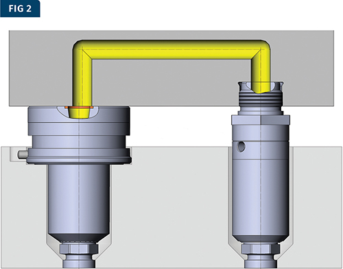
Threaded nozzles, on the other hand, are threaded into the manifold block with their bores being aligned to the manifold bores as an assembly. The complete assembly is designed to slide into the mold at room temperature. As the manifold expands, the nozzles are designed to flex while maintaining perfect alignment of the bores. With this style of system, we can rule out a stagnation point at the nozzle/manifold interface as a result of dimensional tolerance stack-up or variation in operating temperature (Fig. 2).
COLD RUNNER VENTING
One of the most significant advantages of a hot-runner system is the ability to sequence the gates. Large, complex, multi-gated parts often utilize hot-runner systems to allow the gates to be sequenced to fill out the cavity evenly and either eliminate or control the location of the weld lines. On these parts, the hot runner often will gate into cold sprues or short cold runners.
When adjusting the valve-gate sequence to optimize the part, it is very easy to trap air at the delayed hot-runner gates, which can be very difficult to vent. The result is a burn that appears to be coming from the hot-runner gate but is in fact a gas trap at the hot-runner nozzle tip. A simple test when dealing with a burn at a hot-runner gate on a sequentially filled part is to take a shot with all the gates opening at the same time to see if the burn goes away. If the burn immediately goes away, then you can be sure it is a venting issue and then focus on adjusting the sequence instead of treating the problem as a burn coming from the hot runner (see photo).
TROUBLESHOOTING IN THE PRESS
Whenever a problem is discovered while the tool is in the press, some basic troubleshooting should be done prior to removing the tool. Failure to do so is a major lost opportunity to quickly gather critical information that will aid troubleshooting while the tool is out of the press.
As explained previously, burns in hot-runner molds can be very misleading. Even if you believe you know the root cause of the issue, it is always good practice to do some quick process experiments to see which molding parameters affect the problem. Even a change that makes a problem worse still yields valuable data.
The first step should always be to check the purge temperature. It should never be assumed that the melt is at the temperature of the barrel. Screw speed and backpressure can have a huge impact on the actual melt temperature. Reducing them is often the quickest way to cool down the melt and see if it improves the burning problem.
The melt can also pick up a significant amount of heat from shear as if flows through the hot-runner system. Slow down the filling to see if it has any impact on the problem. Even if an acceptable part cannot be molded at the longer fill time, knowing the impact of fill speed is valuable information that can help lead you to the final solution.


Related Content

What to Do About Weak Weld Lines
Weld or knit lines are perhaps the most common and difficult injection molding defect to eliminate.
Read More
How to Optimize Pack & Hold Times for Hot-Runner & Valve-Gated Molds
Applying a scientific method to what is typically a trial-and-error process. Part 2 of 2.
Read More
Best Methods of Molding Undercuts
Producing plastics parts with undercuts presents distinct challenges for molders.
Read More
Are Your Sprue or Parts Sticking? Here Are Some Solutions
When a sprue or part sticks, the result of trying to unstick it is often more scratches or undercuts, making the problem worse and the fix more costly. Here’s how to set up a proper procedure for this sticky wicket.
Read MoreRead Next

Fixing Hot-Runner Filling Imbalances: Take a Systematic Approach
Jumping right in to try to make a fix without a methodical troubleshooting approach is apt to waste a lot of time and perhaps even make things worse. There is a better way.
Read More
Reduce Hot-Runner Downtime With Proper Troubleshooting
Solve your problem faster by adopting a systematic approach. Here’s how to get going.
Read More
Fixing Hot-Runner Filling Imbalances: Take a Systematic Approach
Jumping right in to try to make a fix without a methodical troubleshooting approach is apt to waste a lot of time and perhaps even make things worse. There is a better way.
Read More