
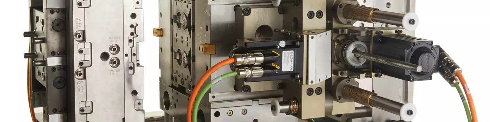


Many segments of the injection molding industry are making a shift towards electrifying the mold, converting a system to use electrical power. In injection molding, this is accomplished by applying servo motors to control the actuation of mold movements such as core pulls, stripper plates and unscrewing racks.
Servo motors can control the actuation of mold movements such as core pulls, stripper plates and unscrewing racks.
Why Make the Switch?
Making the change to electrification is about mitigating risk and improving production. The application of servo motors reduces the chances of bad parts entering the supply chain. Electrification supports a clean molding environment and an increased control of the process with real-time feedback. This feedback provides the data to trace and isolate the root of a problem before it becomes unmanageable.


The most prominent reason for replacing hydraulic actuators on the mold with servo motors is cleanliness. Hydraulic systems are prone to leaking, leading to part contamination, which is a significant concern for cleanroom operations and medical molders.
Molders of food-grade and technical parts have also started to adopt servo solutions in place of hydraulic cylinders. Like medical molders, food-grade and technical-part molders cannot afford the risks associated with contaminated parts entering the supply chain. Hydraulic fluid can adversely react with coatings or lubricants that are part of secondary downstream assembly steps, resulting in scrap and lower yields, so minimizing contaminants is of great interest to all these molders.
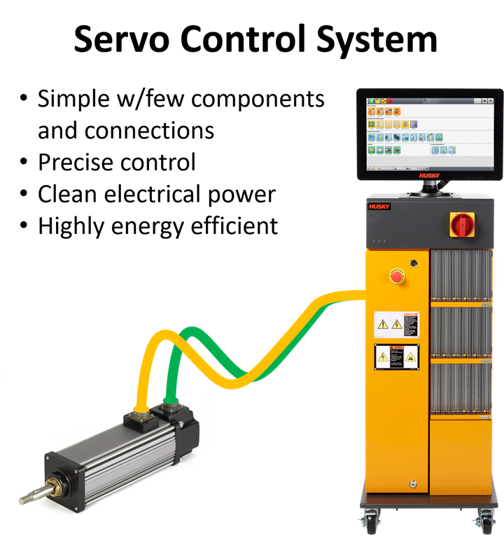
The Servo Advantage
In simple terms, a servo system consists of a controller containing a programmable logic device, I/O modules, and a servo drive unit or amplifier. The controller utilizes cables to deliver power and connect to a sensor device in the motor. This sensor, typically a resolver or absolute encoder, precisely measures the shaft rotation and reports the motor position back to the controller’s drives. The drives will adjust the motor’s current supply to match the controller’s programmed profile based on the sensor device’s feedback.
This closed-loop control gives instant notification if the attached mechanical mechanism changes the behavior of its movement. If something is going out of spec, the operator is alerted immediately. This early warning allows the operator to resolve issues before any significant damage to the mold occurs or part quality is impacted.
Further benefits are achieved by profiling the motion of a servo motor. A motion profile defines how the motor behaves in speed, acceleration, and deceleration for different steps during motion. Each step allows the motor to speed up or slow down, resulting in a smooth, uniform movement that reduces the mechanical stress on components, resulting in longer mold life and increased uptime. This smooth motion can also reduce cycle times by allowing the associated mechanical mechanism to run faster because it is not subjected to the shocks and harsh vibrations created by running a hydraulic system at the same velocity.
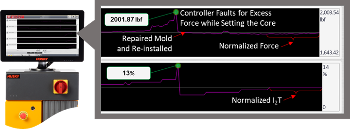
Closed-loop control of the servo motor gives instant notification if the attached mechanical mechanism changes the behavior of its movement.
Another advantage of servo systems is that they are more energy-efficient than their hydraulic counterparts. Hydraulic systems are less efficient because they require a pump to maintain pressure in the lines continuously, so the response is immediate when motion is needed. In contrast, a servo system only requires energy when in motion or holding position because it can deliver power instantaneously.
Designing a Servo System
The transition to electrification can be successful only if the servo system is designed correctly. This effort starts with defining the mechanical characteristics and performance requirements of the mechanism the servo system will be controlling. To properly design an effective servo solution, certain information is required.
Servo systems are more energy-efficient than their hydraulic counterparts.
Number of Axes: The number of axes defines how many servo motors are required for the application. Simply put, one axis equals one motor. This information is essential because it directly impacts cost and the size of the physical servo controller.
Supply Voltage: Knowing the controller’s supply voltage is essential because it can directly impact the motor performance. If the supply voltage is lower than the motor winding voltage, the motor’s speed could be reduced by half. Keep these voltage mismatches in mind when the mold is being built in a region with a higher operating voltage than where it will run production.
Motion Type: The motion type is defined as rotary or linear. Although all servo motors’ output shafts move rotationally, the motion type refers to the downstream mechanical movement. Designs that include mechanisms that translate rotary to linear motion, such as a ballscrew or rack driven by a pinion gear, would be considered linear applications. If the motor drives the attached mechanical mechanism rotationally throughout the design, such as a gear train or belt-and-pulley system that turns cores or mold components, it is a rotary application.
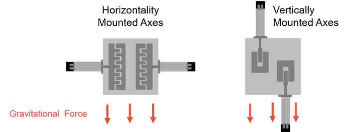
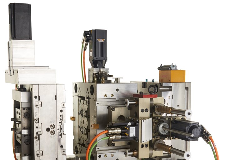
Axis mounting direction—vertical or horizontal—is an important design consideration.
Axis Mounting Direction: For linear applications, the servo motor or actuator’s mounting orientation determines the effects of gravity. Gravity has minimal impact on horizontal mounted axes while having a more significant influence on vertical axes. Depending on the mass of the load and the actuator screw pitch, a brake may be required for holding the moving mechanism in the vertical or set position when the motor is not energized.
Moving Mass: The mass of the mechanism the motor will be moving must be known. This information is used to determine the load’s inertia, critical to determining the motor’s torque or force requirement. Also, be mindful that the motor has internal inertia that must be considered in addition to that of the load. In a rack-and-pinion design, the yoke weight and the attached racks would constitute the load. For gear trains used in rotary applications, each gear’s diameter should be known, with the gears attached to the motor and driving the load being most important.
It is highly recommended that the mold’s solid model is used so all gears can be accounted for and easily measured. Defining the gear transmission ratios is also necessary because this determines the mechanical advantage. The ratios could be such that torque is lost and speed is gained, or force is gained and speed is lost, relative to the motor’s specified performance.
Peak Force or Torque per Axis: The peak force or torque is one of the more critical pieces of information required to correctly size a motor for an application, and one of the most difficult to determine. When gathering this information, be sure to consider the force or torque needed for warm and cold demolding.
Working Stroke or Revolutions: The working stroke is required for linear applications to understand how far the actuator end rod must travel. Always add a buffer to the stroke length to prevent the actuator from bottoming out on itself, leading to premature failure. This buffer will also allow extra travel if needed when fine-tuning the application. For rotary applications, the number of revolutions required to unscrew parts from the core or rotate a spin stack would be necessary.
Total Cycle Time and Servo Movement: Mapping the molding cycle is necessary to ensure the correct motor is specified. Understanding the molding cycle will help define when each move should occur, the speed at which one should execute each move, and how much torque or force is required to make a move. Motion duration is necessary to calculate dwell. Dwell is the time the motor has to cool down before the next move. If the motor can cool down during the cycle, it can deliver peak torque for short durations without overheating. More dwell time could mean a smaller motor is required, resulting in a lower-cost solution.
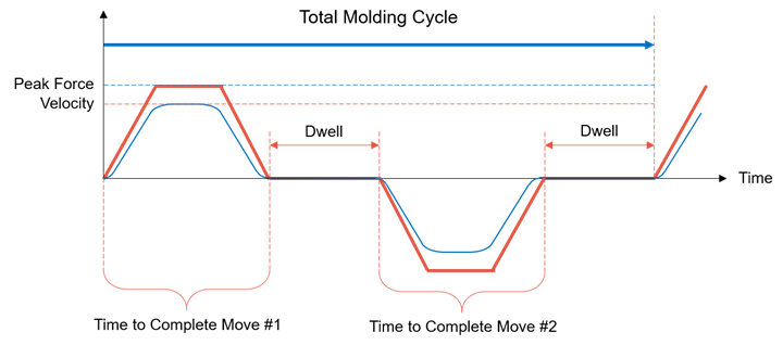
Understanding the molding cycle will help define when, at what speed and with how much torque each move should occur.
Injection Molding Machine Interface: Often ignored, evaluating the available signals on the injection molding machine that the servo controller will use for triggering motion, motion permissions, and interlocking with the machine’s safety gates and emergency stop circuits are crucial to the safety and performance of a servo system. Although there are available standards such as Euromap 67 and Euromap 74, they may not be installed on the machine, and none contain all the necessary signals to interface with a servo controller. For this reason, working with internal machine resources or the machine supplier to develop a signal interface suited to the servo application is essential to ensuring the integration of the servo system goes smoothly.
Getting Started With Servo Systems
The information in this article covers only the minimum required to start sizing a servo system. Although possible, performing hand calculations for these values can be very complicated and tedious. For this reason, it is common to use software programs that automatically apply the proper equations and calculations for sizing. However, the highest probability of success is to find the right partner specializing in injection molding applications.
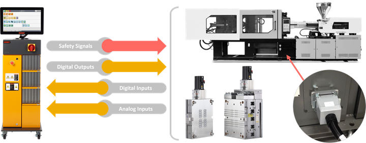
It’s essential to work with internal machine resources or the machine supplier to develop a signal interface suited to the servo application.
ABOUT THE AUTHOR: Matthew Cummings is product manager and technical expert for mold controllers at Husky Injection Molding Systems. His responsibilities include business development, marketing, communications, product life-cycle management, and collaborating with other departments to ensure the product is adequately supported. Having 30 years of industry experience, he joined Husky in 2007 after previously working for Moldflow and American MSI Corp. Prior to his current position, he has held positions in operations, engineering, sales support, and technical service.Contact: (905) 951-5000; mcummings@husky.ca; husky.ca.


Related Content

Why Shoulder Bolts Are Too Important to Ignore (Part 2)
Follow these tips and tricks for a better design.
Read More
How to Start a Hot-Runner Mold That Has No Tip Insulators
Here's a method to assist with efficient dark-to-light color changes on hot-runner systems that are hot-tipped.
Read More
Why Shoulder Bolts Are Too Important to Ignore (Part 1)
These humble but essential fasteners used in injection molds are known by various names and used for a number of purposes.
Read More
How to Select the Right Tool Steel for Mold Cavities
With cavity steel or alloy selection there are many variables that can dictate the best option.
Read MoreRead Next

Precisely Managed Melt Delivery Moved into the Hot Runner
Husky says its new UltraShot injection system miniaturizes the shooting-pot concept of a traditional two-stage injection system—putting it within the mold—to create proximity to the gate that all but eliminates pressure drop.
Read More
Running Cold to Hot: Tipping Point to Convert to a Hot Runner System
As the original melt-delivery system, cold runners still have their place in injection molding, but when demand for a plastic part—and required production—rise, the move to a hot runner can unlock myriad benefits.
Read More
Why (and What) You Need to Dry
Other than polyolefins, almost every other polymer exhibits some level of polarity and therefore can absorb a certain amount of moisture from the atmosphere. Here’s a look at some of these materials, and what needs to be done to dry them.
Read More