

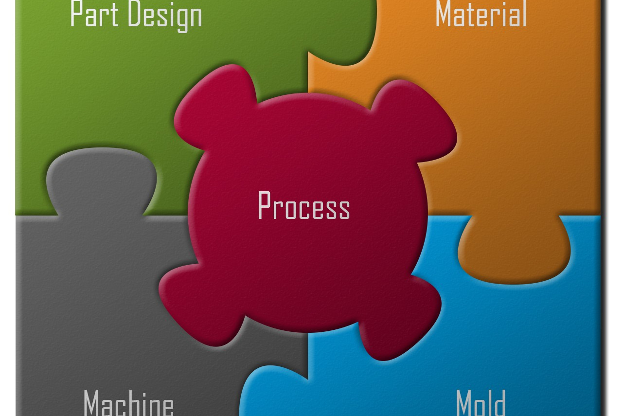
All five variables of injection molding must mate in order to execute a process successfully.

Like stopping a car at exactly the right spot in the garage time after time, the goal in Decoupled Molding is to stop the flow of plastic consistently at the end of cavity.
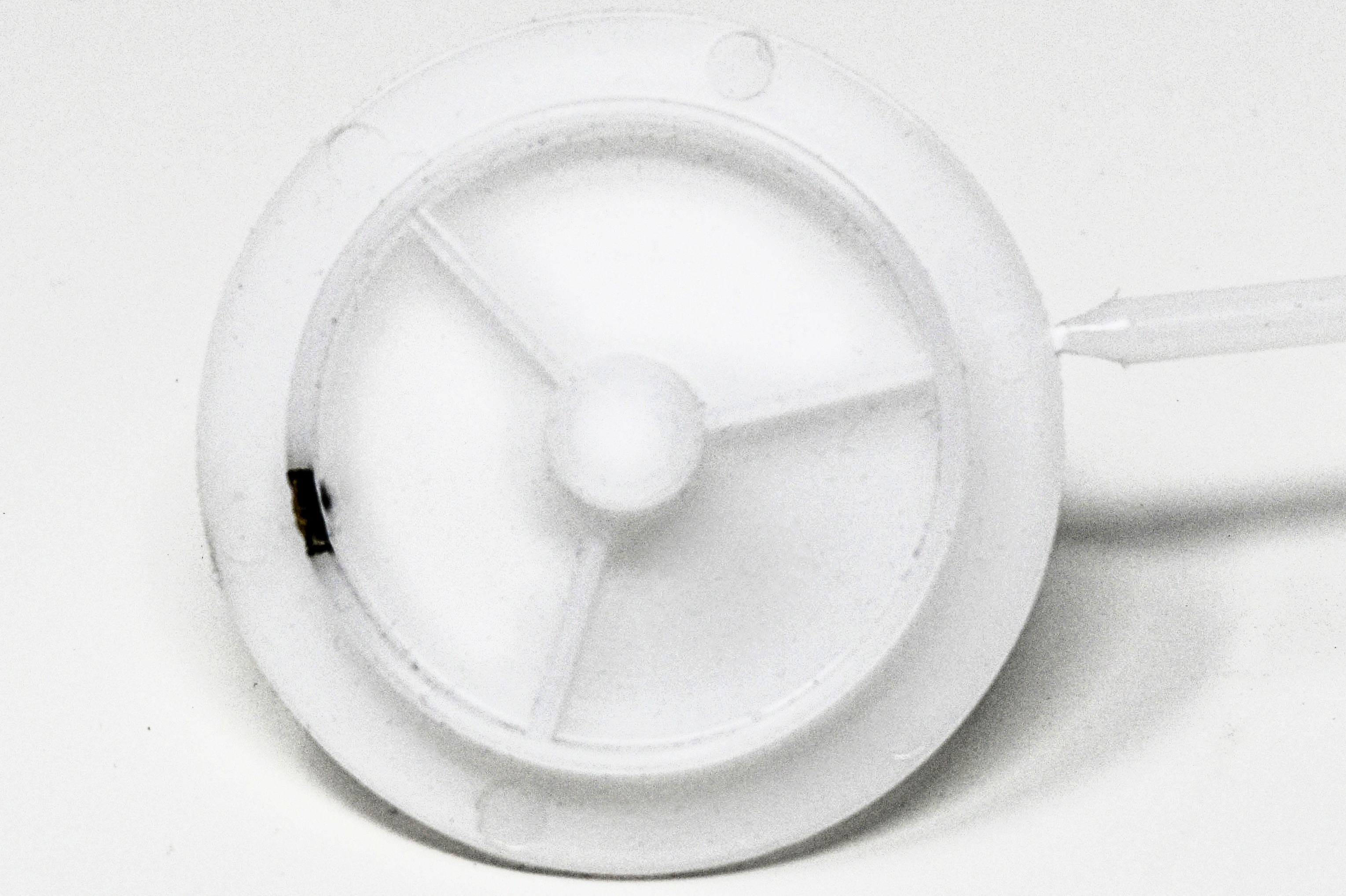
Note the burn mark on this part, made in one cavity of a two-cavity disc mold. Though there are many causes of part defects, decoupling a process makes it easier and faster to diagnose their root causes and identify solutions. In this case the problem was solved not by frantic button pushing, but by collecting and analyzing data.


Late last year, a coworker and I were assisting a third party to process a mold that they hadn’t run before—a disc mold (essentially two round discs). We did some initial calculations and found a press where it would fit. As we were building our process, we noticed that there were burn marks at the end of fill.
In many molding plants, when a processing issue like this arises, operators are typically seen frantically pushing lots of buttons to solve the problem based on their various opinions. However, burns can be traced to one of five areas: part design, material, mold, machine, or process. Regardless of the main cause of the burns, the process is also influenced by the other four areas. Therefore, if you want the process to be successful, all five pieces must fit together nicely. For example, if the part design is not engineered for the material, or the machine cannot produce enough clamp force to support the mold, then the chances of building a robust and repeatable process are unlikely. By making sure that all these pieces fit, you are following a proven methodology or system.


Whether you are relatively new or have been molding for many years, you have probably heard the terms “scientific molding” and “systematic molding.” These terms are often used interchangeably, but there is a subtle difference. Scientific molding is centered around learning about key molding principles and theories. The strategic application of those principles and theories is what is known as systematic molding.
Ask Apple’s Siri, “What does ‘systematic’ mean?” and she’ll respond, “The definition of ‘systematic’ is done or acting according to a fixed plan or system; methodical.” In injection molding, if processors just “button-push” their way through processing, they’ll eventually make a good part. However, molding from a systematic approach cuts the time it takes to build a robust and repeatable process. Using systematic molding techniques often results in decreased machine run time, cycle time, scrap rates, and so much more. The cumulative benefit of these cost reductions leads to increased profits.
Taking a systematic approach involves separating the three stages of the molding process: fill (first stage), pack (second stage) and hold (third stage). Separating the stages is called Decoupled Molding and is the focus of systematic molding. There are two main types of decoupled processes: Decoupled Molding II (DII) and Decoupled Molding (DIII). In a DII process, fill is separated from pack and hold. To accomplish a DII process, during first stage the part is filled to a minimum of 95% visually full and to a maximum of 98% full by part weight before transferring to second stage. This is accomplished by adjusting the transfer position until the desired fill-only part is reached. For a DIII process, pack and hold are also separated. This is generally achieved by transferring based on cavity pressure. Building a DIII process requires extra training, equipment and software.
Imagine decoupling to be like pulling into your garage after work. You’ve suspended a tennis ball from the ceiling to help you know exactly where to park. The tennis ball represents a full shot. Traditional molding would have you drive 45 mph from start to finish. With this method, how many times are you likely to stop exactly at that tennis ball without going out the back wall? Probably not very many. Using a DII process, you’ll drive 45 mph to your driveway and then slow down to 15 mph until you reach the tennis ball. Your chances of stopping at that tennis ball just became a lot more likely, but you can do even better. Using a DIII process, you’ll drive 45 mph to the driveway, 15 mph to the door of the garage, and then slow down to 5 mph until you reach the tennis ball.
So, what is the benefit of processing with Decoupled Molding? When you decouple your processes, you minimize the impact of viscosity fluctuations. Change in material viscosity is a molder’s greatest processing variable and can cause a process to go from producing short shots to parts with flash in the of blink of an eye. Like stopping the car right at the tennis ball in the garage consistently, the goal in Decoupled Molding is to stop the flow of plastic at the end of cavity consistently.
Before you start generating a process, develop machine-performance baselines for each press that will potentially be running the mold. Some studies used to determine this baseline include the following: Injection-Speed Linearity, Check-Ring Repeatability, Load Sensitivity, and Pressure Response. These studies will tell you the current state of the machine to determine whether a particular press should be selected to run the mold. Each study should have an acceptable deviation limit set by your company to use as a type of grading scale. Keep in mind that if a machine’s performance falls outside of the desired deviation limit, it does not necessarily mean that the machine is bad. If you are still able to make good parts within a desired cycle time, then it is perfectly fine to continue processing on that machine. On the flip side, if the machine is producing bad parts, then that mold should not operate in that specific machine.
This baseline machine data will tell you which of your presses is your “limiting” press. For example, if you have three machines where the mold will be used, and one of the presses has a much slower injection rate, build your process using the limitations of the least capable press. When you build your process for the “limiting” press, you accomplish three things:
1. It ensures that the process makes quality parts in the “limiting” press;
2. You know you can transfer those machine values to the other more capable presses;
3. When you transfer the process values, you continue making quality parts.
You can start building your process once you know the capabilities of your machines. Similar to machine baselines, you also create process baselines specific to each mold in order to process “from the plastic’s point of view.” To do this, you must look at the four plastic variables: temperature, flow, pressure and cooling.
Temperature: When logging plastic temperatures, it is critical to document plastic melt temperatures, and not barrel temperatures. Just because barrel temperatures are set at 500 F does not mean the actual plastic temperature will be 500 F. There are three machine settings that will affect plastic temperature: Barrel temperatures (electrical), Screw rpm (mechanical), and backpressure. Generally, a large portion of melt energy comes from the mechanical shear generated via screw rpm. In most cases, you can monitor the plastic temperature by taking a melt temperature at the nozzle. If you’re happy with the results, maintain the settings. If not, then make adjustments.
Flow: The impacts of plastic flow rate are the main focus of the plastic flow variable. Plastic flow is the first stage of a Decoupled Molding process. One of the main reasons plastic flow rate is important is because it has the biggest impact on the material’s viscosity. The faster the material is pushed, the thinner it becomes and the easier it flows. In contrast, the slower the material is pushed, the thicker it becomes and the harder it is to flow. This is known as Non-Newtonian behavior and explains why you might end up with flash when increasing the flow rate from 5 in./sec to 15 in./sec.
When choosing a flow rate or fill speed, select it based on part quality, not machine capability. Just because you have a press that is capable of filling at a rate of 20 in./sec does not mean you should fill at 20 in./sec. There are two tests we use to help determine an optimal flow rate: the Fill Flow Study and the Dynamic Cavity-Imbalance Study. During the Fill Flow Study, you look for defects that appear on the parts when using a range of different speeds. With the Dynamic Cavity-Imbalance Study, you want to see the effect of different speeds on the balance of the cavities. With the results of these two tests, you can choose a flow rate that will yield quality parts.
Pressure: Plastic pressure involves the pressurization stage of the process. This includes both second stage in a DII process (pack and hold) and second stage (pack) and third stage (hold) in a DIII process. Pack focuses on two things: 1) It finishes filling the part and applies pressure to imprint the cavity onto the plastic; and 2) plastic is non-hydrostatic, meaning that the melt does not transmit pressure equally. This is evident when you compare pressures at the screw tip vs. pressure just past the gate cavity (post gate) vs. pressure at the end of cavity. In most cases, you will see that pressure at the screw tip is greater than at post gate. Likewise, you will generally see the post-gate pressure is higher than at the end of cavity during the pack stage.
The other half of plastic pressure is the hold stage. Up to this point in the process, you have filled and packed the part. The last thing you want is to let plastic backflow out of the cavity. To prevent this, hold time and hold pressure are applied. To determine how much time is needed for the gate to freeze—at which point we know the plastic won’t backflow—perform a Gate-Seal Study. This involves increasing the hold-time setting on the machine until you see that the part weights stop increasing, or plateau.
Cooling: The final—and often most overlooked—variable is plastic cooling. Cooling is critical and typically accounts for around 80% of cycle time. How is this possible? If you stop and think about when plastic really starts cooling, you’ll realize that it occurs as soon as the material hits steel. This variable focuses on the means of how plastic cools and includes things like cooling lines and their contents and achieving turbulent flow. A classic yet common issue processors encounter is forgetting to turn the water (coolant) on. Often, this can lead to extended hold times and ultimately longer cycle times. You can do a couple of things to ensure you have water flow. One option would be to monitor coolant flow by installing flow meters within the cooling circuits. Another option is to monitor mold surface temperature. Ideally, we monitor both coolant flow and mold temperature.
Molders and their customers are becoming increasingly data oriented. This business strategy aligns well with utilizing Systematic Molding principles. When you complete studies on machines and molds, you’ll be equipped with the information needed to build robust decoupled processes. The data drives our processing, thus creating greater transparency between companies, customers, and co-workers. As you make changes, you can defend them with data.
Letting data drive your processing decisions also makes troubleshooting so much easier. This is how we systematically tackled our burn issue in the disc mold mentioned earlier. Using decoupled processing, the first thing we did was look at “fill-only parts” by removing second-stage time and pressure. The fill-only parts had no indication of burn. The burn was observed at the end of fill only when we packed the parts. We then decided to remove second stage (pack and hold) again and adjust our short shot so that the part was fuller before transitioning to second stage. As we progressively filled the part out further, we noticed the burn was returning.
With this information, we decided to put a sticky note at the top of the mold at the parting line. Putting the sticky note between the mold halves at the parting line allows the air to properly vent from the cavities (effective, but not recommended). When we did that, the burn went away. This was the final piece of information we needed to isolate the cause of the burn issue. The vents in the mold were not at the proper depth to let air escape from the cavity during fill. To eliminate the burn, we added a second fill speed that was significantly slower than the first speed. This allowed the air to escape before transitioning into pack and hold.
After just 20 min of gathering and examining data, we accomplished two things: 1) We were able to determine the cause of the burn; and 2) We found a way to mold the part without burn. Some might call it witchcraft, and others claim we were plain lucky. But neither is true. Though there are many causes for part defects, decoupling a process makes it faster and easier to systematically diagnose their root causes and identify possible solutions.
By decoupling your processes, you can separate defects by whether they are related to fill or to pressure. Some part defects that commonly relate back to the fill stage would be splay, jetting and burn. On the other hand, warp, sinks, voids and bubbles are more commonly related to pack and hold stages.
Establishing machine and process baselines as well as learning to interpret data do not happen overnight. These things take time, and what works for one molder is not necessarily going to work for another. What you can do is continue to learn from each other’s experiences and trust what your data tells you. Ultimately, continue to apply systematic molding principles because they work to improve processes and, ultimately, profits.


Related Content

Tunnel Gates for Mold Designers, Part 1
Of all the gate types, tunnel gates are the most misunderstood. Here’s what you need to know to choose the best design for your application.
Read More
Why (and What) You Need to Dry
Other than polyolefins, almost every other polymer exhibits some level of polarity and therefore can absorb a certain amount of moisture from the atmosphere. Here’s a look at some of these materials, and what needs to be done to dry them.
Read More
A Simpler Way to Calculate Shot Size vs. Barrel Capacity
Let’s take another look at this seemingly dull but oh-so-crucial topic.
Read More
How to Get Rid of Bubbles in Injection Molding
First find out if they are the result of trapped gas or a vacuum void. Then follow these steps to get rid of them.
Read MoreRead Next

Understanding Melting in Single-Screw Extruders
You can better visualize the melting process by “flipping” the observation point so that the barrel appears to be turning clockwise around a stationary screw.
Read More
Processor Turns to AI to Help Keep Machines Humming
At captive processor McConkey, a new generation of artificial intelligence models, highlighted by ChatGPT, is helping it wade through the shortage of skilled labor and keep its production lines churning out good parts.
Read More
Troubleshooting Screw and Barrel Wear in Extrusion
Extruder screws and barrels will wear over time. If you are seeing a reduction in specific rate and higher discharge temperatures, wear is the likely culprit.
Read More