
What You Need to Know About Blade Ejectors: Part 1
Follow these guidelines to prevent premature wear, flash and galling.


A blade ejector is basically a rectangular ejector pin. It performs the same function as a round ejector pin, which is to help eject a portion of a part. They are most often used at the bottom of a deep rib.
The biggest advantage a blade ejector has is the amount of surface area pushing against the part during ejection. Figure 1 shows a 0.080-in.-wide rib with two 1/16-in. (0.062-in.) round ejector pins and a standard 0.062 × 0.172 in. ejector blade. The blade in this example has almost twice the surface area pushing against the part as the two round pins combined.


A molded part adheres to the core with a certain amount of force. The ejector pins, sleeves, blades, etc. must overcome that force without creating a mark or causing a distortion to the part. The more surface area in contact with the part, the less chance of the part being damaged. Commercially available ejector blades come in an assortment of widths and thicknesses. Therefore, it is always a good idea to use the thickest and widest ejector blade practical. A thicker and wider blade also has less chance of buckling than a thinner and narrower one.
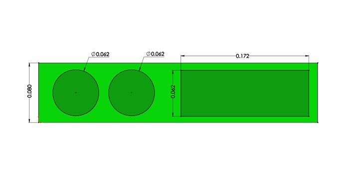
FIG 1 Surface area of ejector pins vs. an ejector blade.
If a rib is thin, such as 1/16 in. or less, and if a protruding boss for a larger-diameter ejector pin is not allowable, a blade ejector is one of your few options. Small-diameter ejector pins will most likely either buckle during ejection, or embed themselves into the rib, as shown in Fig. 2. Despite their obvious advantage of greater surface area, the first thing you should know about blade ejectors, if you don’t have a lot of experience using them, is that you should use them only when it is absolutely necessary. They are much more expensive than standard ejector pins, and there are several important guidelines that should be followed to prevent catastrophic damage to both the blade and the mold.
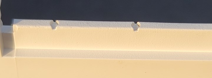
FIG 2 Small-diameter ejector pins embedded into a rib.
Surface Contact
One reason to avoid blade ejectors is surface contact area. A round ejector pin rides in a round hole with a slight clearance around its perimeter. But a round pin is never perfectly centered in its hole. It shifts to one side, which results in a thin line-contact. The same is somewhat true for blade ejectors. They also shift to at least one, usually two sides. But this results in surface contact, which is considerably greater than the line contact on a round ejector pin. Therefore, rectangular ejector blades are subject to wear at a much faster rate than round ejector pins.
If an ejector pin or an ejector blade wears, you simply replace it. But if either a pin or blade wears the hole or slot it rides in … that’s a different story. It is relatively easy and inexpensive to increase the diameter of a worn hole for an ejector pin and install a pin that is a standard 0.005 in. oversized. But if an ejector blade wears out its slot, the slot needs to be increased and a custom blade needs to be installed, or you need to weld the worn-out slot and machine it to its original size. Depending on how the blade was installed, it may not even be possible to repair by welding.
Precision
Years ago, the width and thickness of OTS (off-the-shelf) ejector blades were not very accurate and had to be re-ground to size. According to the domestic websites I reviewed, those tolerances have gotten much better and are typically +0.0000 in. to -0.0003 or -0.0006 in. A few of the offshore mold-supply companies offer tolerances as low as +0.0000 to -0.0001 in. This could be important when molding very low-viscosity materials, such as nylon. But keep in mind that people make mistakes. You would be wise to apply the old Russian proverb of “trust but verify” (No, former President Ronald Reagan did not invent this saying.) All component parts should be measured before blindly installing them into a mold.
All ejector blades should be keyed.
I know a tool shop that intentional grinds a few thousandths off all four sides of brand-new ejector blades. Their reasoning is when the slot or hole wears out, they don’t have to order a custom blade after repairing the mold. Effectively, this moldmaker starts off with a 0.005-in. undersized blade—knowing that it will be cost-effective in the future.
Surface Finish
One important aspect when selecting a blade ejector is the surface finish—actually surface roughness—which is usually specified in Ra units. Ra is the arithmetic average of the surface heights measured across the peaks and valleys of a surface with a profilometer. The surface finish plays a couple of important rolls in determining the performance of an object. Objects with high Ra values have irregularities on the surface, which can create nucleation sites for cracks and corrosion to form. Rougher surfaces also have higher coefficients of friction, which cause them to get hot, wear faster and potentially gall. When the surface finish of both components is very smooth, any applied lubricant creates a fine film between the components, which helps prevent them from touching one another—like when the tires on your car hydroplane in the rain. This is called elastohydrodynamic lubrication, or EHL.
Offshore component parts are made to various different standards, such as DIN (German Institute for Standardization), JAP (Japanese Standards Association), JIS (Japanese Industrial Standards), or Euro Metric, which all have metric dimensions and tolerances. When you evaluate the surface-finish rating of any component, keep in mind that there is a huge difference between Ra in microinches and in micrometers. If the specifications of the component are in inches, the surface finish is correspondingly in microinches. Conversely, for DIN, JIS and other metric specifications, the Ra surface finish is in micrometers; 1 microinch (μin.) = 0.0254 micrometers (μm). For example, an English rating of 4.0 μin. Ra is equal to a metric rating of 0.10 μm. Ra.
Installation Methods
There are four common methods of installing an ejector blade in a mold, as shown in Fig. 3. The worst method is when a portion of the blade rides in more than one mold component. The odds of perfectly aligning the machined slots are slim to none. This will cause accelerated wear and down-flash. Another method is to install the entire width of the blade in one component. While this is an acceptable method, it is difficult to repair. It cannot be welded, but it can be ground or wire EDM-ed to a larger size.
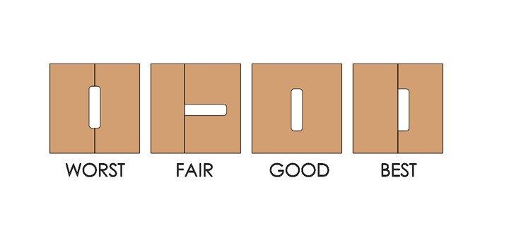
FIG 3 Four common methods of installing an ejector blade.
A very common method of installing ejector blades is in a wire-EDM hole. This is a fast and relatively inexpensive method, but again, not an easy method to repair. One advantage to this method is that a fine EDM finish is sufficient to retain a very thin film of lubricant, which helps reduce the rate of wear. The best method is to machine a wide but shallow slot in one mold component. This type of installation is the easiest to repair if it wears. It is also the easiest to adjust the clearance to get good venting without any down-flash.
Location
Despite what you may believe, have read or been taught, an ejector blade should never be flush with the edge of a rib or a part. Figure 4 is an example of a poorly located blade. It should be set back a minimum of 0.005 in. from any edge or corner. There are three reasons for this. The first is that you want a small amount of plastic to be in a blind corner. This helps prevent down-flash. The second reason is that if the ejector blade is even slightly bent or deflects to the side during ejection, you don’t want the sharp edge of the blade scraping against the side of the core. The third reason is that it is easier for a toolmaker to take a measurement from a small step than it is from a smooth transition.
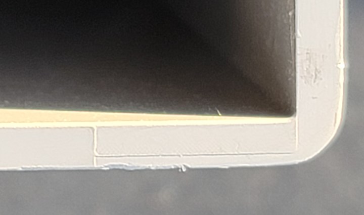
FIG 4 Example of poor ejector-blade location.
Orientation
Unless there is a special contour machined into the face of a blade ejector, most mold designers don’t feel it is necessary for the heads to be keyed or oriented. They assume the blade is self-aligning. While that may be true, why would you want the surfaces of the blade, which are subject to wear, to be responsible for its alignment? The Japanese understand this and offer various contoured head styles as standards, as in Fig. 5. Additionally, any mold with ejector blades should be guided. Heavy, sagging ejector plates cause the pins, sleeves and blades to be misaligned and prematurely wear or gall.
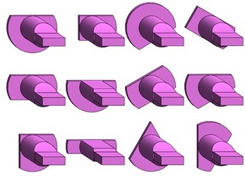
FIG 5 Various Japanese head contours to aid alignment of ejector blades.
Shoulder Length
The length of the shoulder on a commercially available blade ejector can be as short as 5/8 in. to as long as 5-1/4 in. The length you select is extremely important. Ideally, you want the shoulder of the ejector blade to be engaged at least 1/8 in. into the back of the B-retainer plate when the ejector plate is in the retracted position. This usually requires the B-retainer plate to be thicker than the ejector stroke. This B-retainer engagement method is the same as you would use with a small-diameter shouldered ejector pin, and for the same reason—to prevent buckling and breaking.
About the Author: Jim Fattori is a third-generation molder with more than 40 years of experience in engineering and project management for custom and captive molders. He is the founder of Injection Mold Consulting LLC in Pennsylvania. Contact: jim@injectionmoldconsulting.com;
injectionmoldconsulting.com


Related Content

How to Set Barrel Zone Temps in Injection Molding
Start by picking a target melt temperature, and double-check data sheets for the resin supplier’s recommendations. Now for the rest...
Read More
The Effects of Temperature
The polymers we work with follow the same principles as the body: the hotter the environment becomes, the less performance we can expect.
Read More
The Importance of Melt & Mold Temperature
Molders should realize how significantly process conditions can influence the final properties of the part.
Read More
Tunnel Gates for Mold Designers, Part 1
Of all the gate types, tunnel gates are the most misunderstood. Here’s what you need to know to choose the best design for your application.
Read MoreRead Next

Three Key Decisions for an Optimal Ejection System
When determining the best ejection option for a tool, molders must consider the ejector’s surface area, location and style.
Read More
Tooling: What You Need to Know About Jump Gates
Many molders don’t care for jump gates because they have to process around them. But here are some tricks of the trade.
Read More
Tooling: The Lowdown on Guided Ejection Systems
When, where, how and why to use them.
Read More