


Most extrusion lines for pipe or tubing begin with very basic concerns: How do I process this material into this product with the speed and efficiency needed to make a ROI? Ultimately, these concerns get translated into a series of requirements, then ultimately into material specifications and a system of equipment: an extruder, die, sizing method, calibration tooling, cooling system, puller for speed control, and the rest.
Sometimes, processors can develop and purchase an entire line at one time—perfectly matched to material, product, and current production requirements. And, if they are fortunate and successful, they can leverage that line to produce high-quality product for a great customer for a long, long time.


Yet at other times, processors may want to react to business and competitive needs by adapting existing extrusion equipment and tooling. The reasons are many: the need for increased production or profitability, customer gains or losses, changes in product specifications or dimensions, the need to produce different sizes of an existing product, or a change in material suppliers.
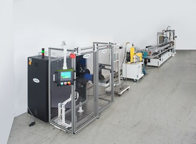
Downstream view of a typical medical tubing line for small-diam. tubing. At the end of the line is an automatic coiling system.
But there are risks and difficulties in adapting existing tooling and equipment, and results may produce problems rather than the cost savings that were intended. Below are a number of situations that we have found are common in the experience of pipe and tube extruders, discussion of the types of problems and questions that arise from them, and suggestions for resolving them with a minimum of difficulty.
The Ideal: Everything Matches Up
To see what can go wrong when changes are made to pipe and tube extrusion equipment, it is important to understand first what needs to be “right” in order for it to work properly. Ideally, any new extrusion line is designed to process a specific material at a specific speed, through a specific die at a specific temperature, and calibrate it to a controlled size through properly designed tooling with an adequate cooling process. Everything is in balance:
• Extruder is appropriate for material mix and production rate;
• Die dimensions are suited to material characteristics and product size;
• Drawdown rate is calculated, so predicted size of extrudate cone matches inlet of sizing tooling;
• Proper sizing method selected, calibration tooling prepared, with cooling adequate to product requirements;
• Production runs smoothly at a selected line speed; line is stable.
Reality: Constant Changes, Daily Challenges
So, what could possibly go wrong with this perfect picture? What are the common situations that processors encounter that can pose extrusion challenges or lead to problems or miscalculations? Can processors respond to those problems by adjusting or adapting capacity? Or, are there times where it’s wiser (or necessary) to invest and retool to get the product quality and ROI that are needed?
1. Change Tube or Pipe Dimensions: Frequently, processors of specialty pipe or tube need to make small dimensional changes in a product or produce a slightly different size using the same material. For example, a tubing maker that makes 3/8-in. tubing (0.3750 in. diam), might get an order for ¼-in. tubing (0.25 in. diam). Rather than invest right away in a new die, the processor decides to see if the existing 0.3750-in. die can do the job with the help of new calibration tooling. Experience teaches that, in some cases, it is possible to use a die designed for a larger diameter product to produce a smaller diameter product. But the ability to do so is highly dependent on the material. Materials that exhibit a high degree of drawdown are very forgiving of size reductions. Here are a couple of examples:
Many medical tube makers are familiar with Pebax (Arkema’s polyether block amide), a highly viscous TPE material with a high level of drawdown. A small, thin-wall tube (0.125 in. OD × 0.008 in. wall) will use a drawdown of 50% or more, since the material is more viscous and pulls down quickly as it leaves the hot die. So, it is certainly possible to use a 0.375-in. die to produce a ¼-in. tube using that material.
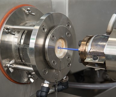
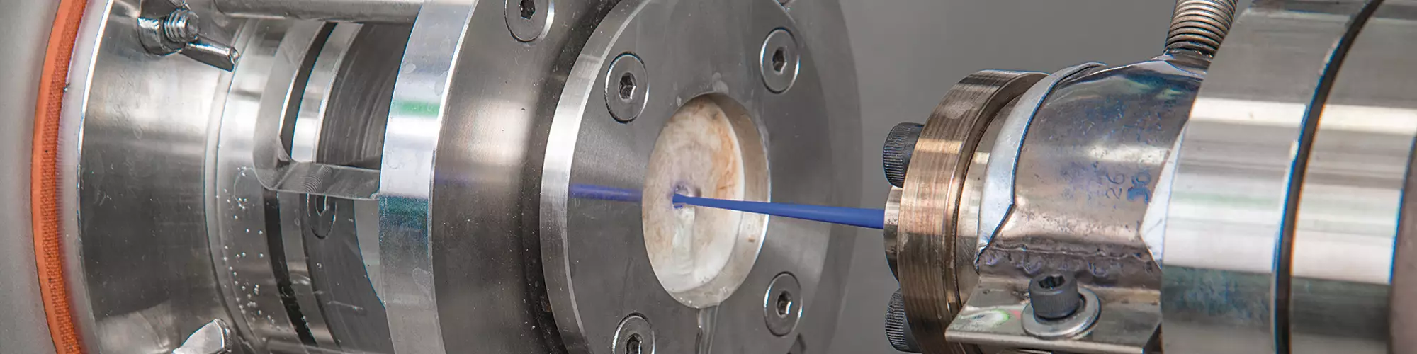
Small-diam. tubing enters the die head, then draws down slightly in the short space between the die and a water-filled, non-contact sizing chamber at the entrance to the vacuum-cooling tank.
A similar, but more challenging size-reduction task might involve using a 2-in. PE die, plus new sizing tooling, to make a run of 1.5-in. pipe. This is more difficult to manage because the PE has a more moderate degree of drawdown. So, there will be some tradeoffs, like slower line speed or the threat of greater process instability. In this case, going from 2-in. to 1.5-in. pipe might mean that you’ve got to pull the calibrator away from the die to give the material a chance to draw down so that it will pass into calibration tooling that’s appropriate to size a 1.5-in. tube. Otherwise, the cone of the extrudate is going to “overpack” the calibrator opening, so that either it occasionally has to fold up to get through—creating tube irregularities downstream—or it won’t get through at all.
So, it is possible to “go smaller” in some cases, based on the material you are extruding. One case where it would not be possible involves a material like rigid PVC. The drawdown rate of that material is so low that you could never achieve a 2-in. to 1.5-in. size reduction. You’d need a new die and new tooling.
2. Increase Production Rate/Speed: When a line is working well, there’s always the question: “Can it continue to produce—but at a higher rate? The answer is, once again, that it depends on the material you are extruding and the dimensions of the finished product. Experience demonstrates that line-speed increases of up to 20% may be possible if you incrementally increase both puller and extruder speed—and if you’re running materials that will tolerate the change—i.e., materials that don’t have high drawdown and swell, such as PE, PP or other polyolefins.
Of course, if you elect to boost line speed and extruder output, you are raising the risk of process instability. Higher extruder RPMs will tend to increase material shear in essentially the same way as if you raised the temperature profile of the material. Boosting line speed may also require you to adjust the amount of material going into the extruded pipe or tube, or adapt the “adjusted size” of the contact tooling, since higher line speeds are associated with greater shrinkage of the end product.
If you elect to boost line speed and extruder output, you are raising the risk of process instability
3. Change Material Supplier: Processors must continually evaluate the quality of the materials they buy, together with the capabilities of the suppliers and manufacturers that provide them. And sometimes processors decide to make changes that can have an effect on the stability and performance of tube and pipe extrusion lines.
With “identical” types and grades of material, small variances in key characteristics can be sufficient to upset pipe and tube extrusion processes and require time-consuming adjustments. For example, a processor who is making nylon tubing for a new customer might select a better grade of material. And, based on their experience with that material, the processor’s extrusion team sources tooling and “dials in” the line to perfection.
Later on, to take advantage of a great price, the processor sources material from a different supplier. But it may not pay off: Extrusion efficiency suffers because the “identical material” is not quite identical—it has a broader molecular-weight distribution. As a result, it has a greater tendency to swell upon exiting the die, causing periodic overpacking of the calibration tool and tube wall inconsistencies when excess extrudate “folds in” and goes through. Finally, after numerous adjustments and plenty of scrap, the drawdown problem is corrected and the line as is stabilized. (If this material switch had happened in reverse—the lack of expected swell would also have caused drawdown problems, with the extrudate being unable to “fill” the calibrator, which was built with the previous material in mind.)
If you want to extrude with consistency, you have to buy materials with consistency.
The lesson here is pretty simple: If you want to extrude with consistency, you have to buy materials with consistency. Develop a window of tolerance for the molecular-weight distribution of materials you buy, and stick to it.
4. Get Sizing and Calibration Right: As with the rest of the tube and pipe extrusion process, experience with sizing demonstrates that there are right ways and wrong ways, with many of the rights and wrongs being material dependent.
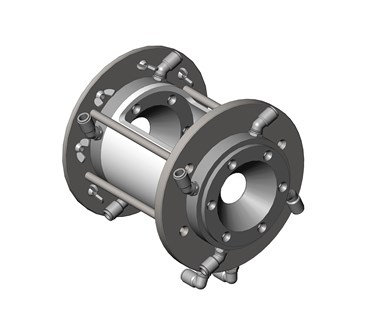
Typical design of a non-contact sizing chamber equipped with an entrance-water well.
Sizing a tube or pipe takes place within a calibrator. A calibrator is a heat exchanger that enables the use of contact, non-contact or hybrid sizing methods to control the OD, ID and wall thickness of the product. The sizing method sets the outer skin of the product as initial cooling takes place. Providing the proper amount of total cooling residence time is vital to ensure the final dimensions of the product, since product shrinkage continues until cooling is complete. General cooling guidelines require approximately 30 sec of cooling time for thin to medium wall thicknesses up to 0.060 in. and 1 min or more for up to 0.100 in.
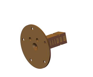
The horizontal split in this sleeve calibrator (rectangular section) allows the top to be lifted for proper positioning of the extrudate, then fixed in place when production begins. It also allows water to enter for lubrication, while large slots provide increased contact area for heat transfer within the vacuum-cooling tank.
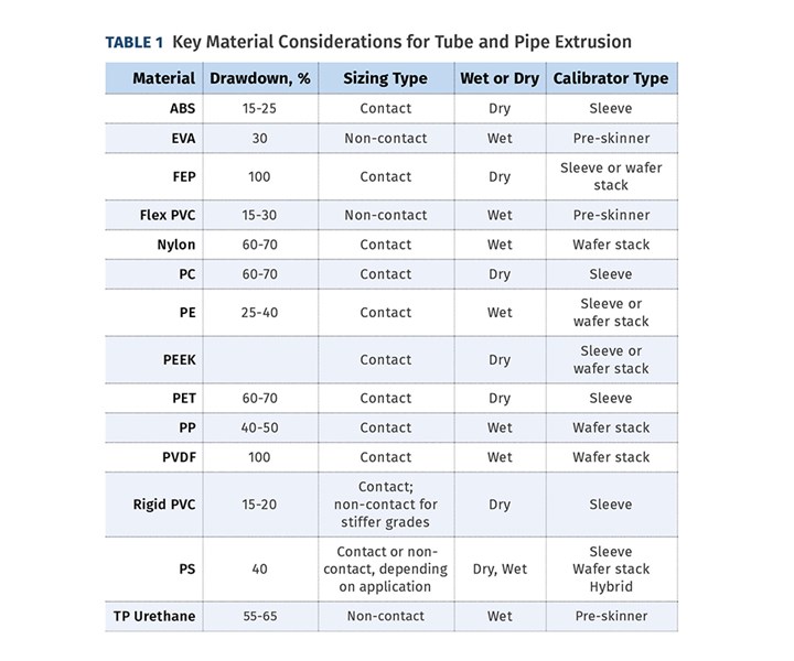
Previously, we noted the importance of calculating the drawdown of the extrudate cone to match the entrance to the calibrator. Getting that dimension right—and matching the correct sizing approach, tooling, and water/lubrication requirements for your material type—are absolutely critical to smooth downstream extrusion (see Table 1).
If you don’t get them right, you’ll constantly struggle with:
• Slower-than-expected production rates and inability to get line speed “right”;
• “Overpacking” the sizing tool;
• Stick/slip inconsistencies in surface finish, including “chatter” marks from lack of lubrication.
• Unacceptable dimensional variability, resulting in the constant need to “tweak” settings.
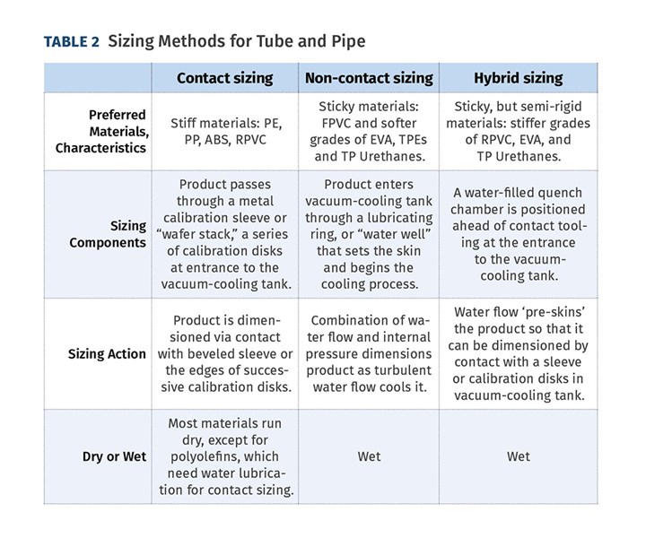
Of the three approaches shown in Table 2, contact and non-contact sizing methods are by far the more common. Non-contact and hybrid sizing methods are used to size “sticky” materials that require water lubrication to run smoothly into the vacuum-cooling tank. In the case of hybrid sizing, initial contact with water takes place in a water-filled quench chamber positioned just ahead of the vacuum-cooling tank. The chamber “pre-skins” the product before it enters the cooling tank and undergoes conventional contact sizing.
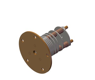
A wafer-stack calibrator aligns a series of calibration disks, clustering them more closely where the hot extrudate enters to prevent sagging, then spacing them farther apart to reduce friction as the tube cools and firms.
Non-contact sizing is the most forgiving with regard to slight changes in product dimensions. Because water, not metal, is making contact with the tube, the tube diameter could increase by perhaps 0.020 to 0.030 in. without the need to change the lubricating ring in the water well. However, contact sizing and tooling are much less forgiving. Making a larger-diameter product that must be contact-sized always requires new tooling, machined to the “adjusted” size of the tube at successive points in the process as the tube shrinks to finished size.
Non-contact sizing is the most forgiving with regard to slight changes in product dimensions.
The biggest problems in sizing occur when people mistakenly employ contact sizing tooling when a non-contact approach is needed. Running sticky, flexible materials through a contact die by mistake is a recipe for a messy overpack or “chatter” marks from the constant stick/slip of the product caused by lack of lubricant on the tooling surface.
Another error involves forgetting or becoming confused about which materials must run “wet”—with a water well for lubrication—and those that don’t. For example, it is essential to run polyolefins “wet,” using a water well, or they won’t tolerate contact sizing. However, if you then switch to a more rigid material, such as PVC, but fail to remove the water well, you will cause dimensional problems because exposing the PVC to water before it is contact-sized in the vacuum chamber is going to start “freezing” its dimensions prematurely.
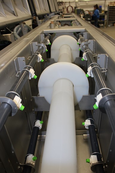
The open lid of a vacuum-sizing tank shows a larger-diam. pipe passing through guides made of UHMW-PE, a material chosen for its lubricity. The guides prevent sagging and aid in size control as the pipe undergoes vacuum sizing and spray cooling.
To many processors, tube or pipe extrusion still looks and feels a lot like an art, since there seem to be so many judgments to be made, so many factors, large and small, to “get right” before a process will work properly. Yet, if you organize and leverage design, materials, and production experience, you may find it possible not only to master this process for tube and pipe products you’re currently making, but to cost-effectively stretch the capabilities of your equipment and processes to achieve even greater flexibility, productivity, and output.
Sometimes, you’ll need new equipment, new dies or tooling, or improved controls to get the job done. But not always. In our experience, many processors are surprised at what they can learn and accomplish.
About the Authors: Ernie Preiato & Dave Czarnik
Ernie Preiato is v.p. extrusion for the Conair Group. Contact 724-584-5423; epreiato@conairgroup.com . Dave Czarnik is R&D /lab manager at Conair’s extrusion laboratory in Pinconning, Mich. Contact 989-460-1805; dczarnik@conairgroup.com; conairgroup.com.


Related Content

Hot Runners: A View from the Bottom Up
Addressing hot-runner benefits, improvements, and everyday issues from the perspective of decades of experience with probably every brand on the market. Part 1 of 2.
Read More
The Effects of Temperature
The polymers we work with follow the same principles as the body: the hotter the environment becomes, the less performance we can expect.
Read More
Solve Four Common Problems in PET Stretch-Blow Molding
Here’s a quick guide to fixing four nettlesome problems in processing PET bottles.
Read More
How to Optimize Pack & Hold Times for Hot-Runner & Valve-Gated Molds
Applying a scientific method to what is typically a trial-and-error process. Part 2 of 2.
Read MoreRead Next

Conair, Partners Run TPE Tubing, ABS 3D Filament at Medical Show
Conair joins Davis-Standard and Zumbach to demo complete system that switched between tubing and filament runs at Plastec West Show in California.
Read More
Four Keys to Consistent Tubing
Because of their use in critical applications, processors of medical tubing have little or no room for error.
Read More
Israeli Pipe Processor Adds Potent Single-Screw Extruder
Billed as ideal for large-diam. pipes, new extruder provides processor with higher output and better quality while consuming less power.
Read More