


Today’s modern manufacturing processes utilize loss-in-weight (LIW) feeders as the automated dispensing technology for dry bulk solids. The most current feeding technologies have evolved in many aspects through improved control and design features with an emphasis on process robustness and intelligence. It is expected that feeder controls can easily connect to industrial networks and key process data, which has become a critical criterion in evaluating not only feeder performance but also real-time indication of the complete process.
This article will address what a processor should consider when evaluating his current feeding equipment and the feeder’s ability to monitor, trend and react to process variations. The availability of this data and its management in accordance with Industry 4.0 automation can allow the user to adapt to future manufacturing requirements, which can include greater traceability, flexibility, adaptability and overall effectiveness.


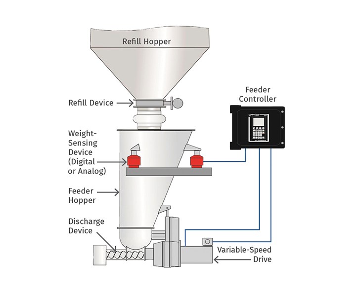 FIG 1 The LIW feeder consists of a feed hopper, refill device, discharge device with a variable-speed drive, weight-sensing device (digital or analog) and controller. A feeder operator sets the material feed rate (setpoint) by sending information to the feeder’s controller.
How a Loss-in-Weight Feeder Works
The LIW feeder consists of a feed hopper, refill device, discharge device with a variable-speed drive, weight-sensing device (either digital or analog), and controller (Fig 1). A feeder operator sets the material feed rate (setpoint) by sending information to the feeder’s controller.
When the feeder is in operation, the discharge device draws material from the feed hopper and meters it to the downstream process. The weight-sensing device continuously reports the material weight in the hopper (net weight) to the controller. The controller calculates an actual feed rate based on the loss in net weight, compares it to the setpoint, and increases or decreases the discharge device’s drive speed to accelerate or slow the net-weight change (loss of material in the hopper) so the feed rate matches the setpoint.
To prevent feeding interruptions, the controller periodically commands the refill device to refill the feed hopper with material. During each brief refill cycle, the net-weight signal from the hopper is increasing, so it can’t be used as a control signal to determine how much material is being delivered to the process. To compensate for this, the LIW feeder temporarily operates in volumetric mode during refill.
The feeder controller can be integrated into a supervisory process-control system that monitors all the feeders and other equipment in your process. The following information explains how data collected by the LIW feeder can help you detect process problems early, ensure product quality, and find setup errors before startup.
Improved Productivity by Trending Feeder Performance
The LIW feeder’s ability to collect process data in real time can help you catch small process problems before they become big ones. Today’s advanced controllers can include communication via a wide variety of protocols, with some even including built-in Ethernet and optional WiFi modules. The capacity of newer controllers can store historical data records for an extended period of time. This data can include the feeder’s feed rate, net weight, and drive-speed-to-feed-rate relationship (called the feed factor). Typical plots of such data are shown in Fig. 2 with key trended parameters as follows:
The LIW feeder’s ability to collect process data in real time can help you catch small process problems before they become big ones.
Feed Rate: The feed rate (sometimes called mass flow) is the most important data provided by your feeder controller. The feed rate’s deviation from your setpoint ultimately determines whether you are producing good product or waste. Typically, the feed rate should deviate only slightly from your setpoint, as shown in Fig. 2 (top graph), and any deviations should be centered around the setpoint. A feed rate that is consistently too high or too low can indicate that the feeder controller is improperly configured, or worse, that your LIW feeder has been improperly set up for the material. Undetected and uncorrected feed-rate errors can result in consistently out-of-spec product and potential waste of valuable ingredients. This problem can be corrected by setting proper alarm limits in the feeder controller and, if possible, plotting feed-rate trends so you can detect and correct problems before they reach critical levels.
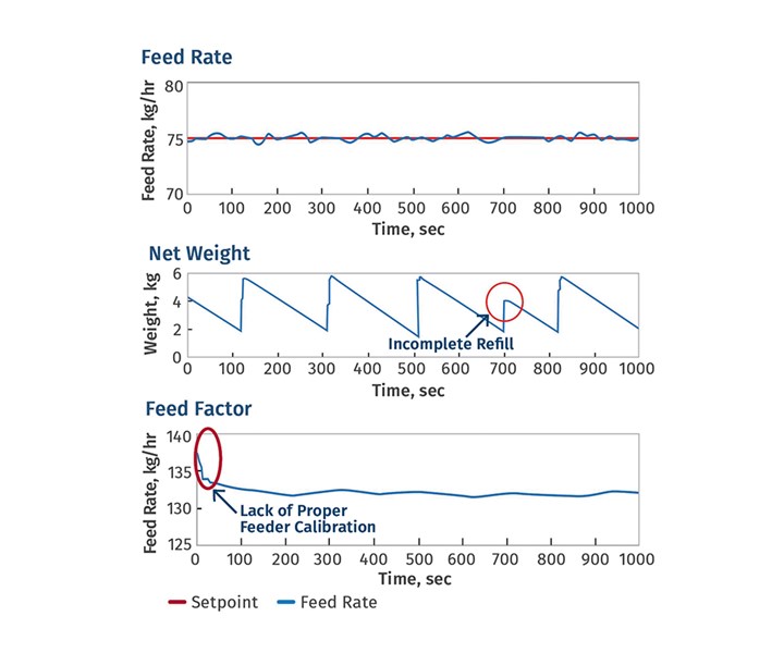 FIG 2 Data commonly collected by LIW feeder.
Net Weight: The net weight sensed by the feeder determines how the feeder controller must adjust the discharge device’s drive speed to achieve your desired feed rate. Yet many users overlook the valuable data that can be collected by observing and plotting the feeder’s net-weight trends. The center graph on Fig. 2 shows a problem detected by observing net weight during a feeding run: After about 700 sec of feeding, one refill cycle was incomplete and failed to adequately fill the hopper, most likely because of problems with the refill equipment or upstream material handling.
Although this LIW feeder continued to operate and feed normally, such an incomplete refill cycle can be a serious problem. Because the feeder is temporarily operating in volumetric mode during refill, and incomplete refill cycles require the feed hopper to be refilled more frequently, the feeder is operating for a much greater time in volumetric mode. By doing so, the feeder is not measuring actual LIW and is only reacting volumetrically. Volumetric operation delivers a certain volume of material per unit time. It does not account for any dynamic changes occurring in the feeder hopper such as variations in the material’s density, formations of rat holes, or material bridges.
These dynamics often result in a much lower feed-rate accuracy. You can detect these upstream material-handling problems and prevent them from affecting product quality by using information from your LIW feeder. One way is to select a feeder controller that can prevent feed-rate inaccuracy during refills by storing information about the proper drive speed for a given net weight and setpoint. This allows the controller to take cues from past net-weight measurements and accurately control feeding during refill.
Feed Factor: The controller must estimate the relationship between your feeder’s drive speed and the material feed rate for your discharge device and material. This drive-speed-to-feed-rate relationship, which is really a measure of your feeder’s volumetric feeding capacity, is called the feed factor and is plotted in tghe bottom graph in Fig 2. Your LIW feeder’s setpoint must be somewhat under the estimated maximum feed rate to ensure that the feeder can consistently achieve your setpoint. If the maximum setpoint is at or too near the upper limit of what the feeder can achieve, the feeder may not be able to reach the setpoint.
Some users think of the feed factor as a one-time measurement to ensure that the feeder they select has enough full-scale capacity. However, knowing the feed factor, updated in real time during feeding, can help detect feeding problems early and prevent large feed-rate inaccuracies. It can also help maintain the proper feed rate during refill. Since material characteristics and operating conditions can vary during a feed run, the feed factor will change slightly while your feeder is running. If the trend shows large changes, however, this can indicate material density changes and other potential problems.
Knowing the feed factor, updated in real time during feeding, can help detect feeding problems early and prevent large feed- rate inaccuracies.
For instance, if the estimated maximum feed rate suddenly increases after the LIW feeder is refilled, the material density may have changed because of humidity or other contamination. If the feed factor for a LIW feeder equipped with a screw discharge device steadily decreases over time while the drive power to maintain the proper feed rate increases, the material may be building up on the screw and the feeder may be losing efficiency. This indicates that the feeder should be cleaned or receive preventive maintenance.
Improving Reliability
Any LIW process controller requires accurate high-speed measurement of material weight changes in order to provide optimal feeder control and performance, especially on a second-to-second basis. The weighing system must also be able to filter out erroneous measurements due to in-plant vibrations or disturbances and be stable over changes in process material temperatures or ambient shop temperatures. To distinguish between the load to be measured and the forces induced by vibration, sophisticated digital filtering may be employed to identify and extract frequency components characteristic of in-plant vibration.
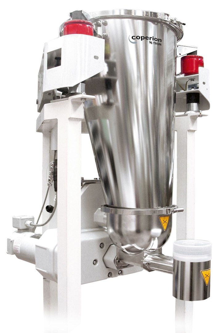
FIG 3 LIW feeder suspended on load cells.
There are two types of weighing technologies typically used in LIW feeders: analog strain gauge and digital vibrating wire. The higher the resolution of weight measurement and the faster those weight measurements are taken, the better the information that will be provided to the control algorithm and the better any vibration-filtering algorithm will work. For example, today’s load-cell (Fig. 3) and controller technologies are available with high resolution and abilities to sample the weight signal up to 50 times/sec (Fig 4). In addition, almost all weighing systems provide temperature compensation.
Today’s load-cell and controller technologies are available with high resolution and abilities to sample the weight signal up to 50 times/sec.
Load-Cell Resolution
When required sample durations are measured in seconds rather than minutes, the resolution of the feeder’s weighing system becomes a major determinant of performance potential. For example, a typical scale with an analog load cell for feeding bulk solids at low mass-flow rates can have a weighing range of 32 kg and a resolution of 1:65,000. This scale can detect approximately 500-mg weight changes. Typically weight changes per second should be approximately five times higher than the minimum resolution which is equivalent to 2.5 g/sec (9 kg/hr).
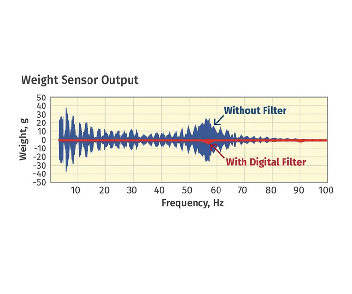
FIG 4 Today’s load-cell and controller technologies are available with high resolution and abilities to sample the weight signal up to 50 times/sec.
When feeding at this rate, it takes the controller 20 sec to detect whether the setpoint is reached within a deviation of ±1%. If the mass-flow rate is below 9 kg/hr it becomes even more difficult to detect improvements of gravimetric control versus volumetric control. Therefore, any mass-flow rate below 9 kg/hr may not even see a significant improvement with gravimetric control.
Conversely, a platform scale with a digital load cell with a weighing range of 24 kg and a resolution of 1:4 million can actually detect 6-mg weight changes. The limit value can therefore be reduced from 9 kg/hr to approximately 108 gm/hr. Therefore, at high or low mass-flow rates, for any processor requiring the highest level of feeder performance over short time scales, weighing resolution should be a major focal point in consideration and evaluation of potential feeding technologies.
Improved Robustness
In addition to those control and load-cell options that help improve process measurement as well as process trending, there are also control options for LIW feeder technology that aid in assisting with adverse effects of external pressures as well as in utilizing vibration for assisting material flow.
In the case of external pressures, for example, a feeder’s refill cycle increases air pressure in the hopper due to the sudden inflow of material. Any positive air pressure acts equally towards all sides and pushes up on the hopper lid and the refill valve. Due to the inlet opening, forces acting upward on the lid are lower than those acting downward oppositely on the floor of the hopper. The higher forces acting down result in an increase in the weight signal. The LIW controller would interpret the increased weight signal to mean that mass flow is slowing and react by erroneously increasing the feeder output creating a mass-flow error.
Hopper-pressure issues can also have other causes, such as a clogged vent filter, a dust-collection system connected to the hopper vent, or a nitrogen blanket applied to the hopper.
Conversely, a pressure fluctuation at the feeder discharge also distorts the feeder’s weight signal if the outlet is sealed with a cap, or includes a clogged vent filter. Increased pressure in the discharge tube pushes upward, which also pushes up on the feeder and reduces the measured weight.
Typically, these troublesome pressure fluctuations have been compensated for by mechanical means. Alternatively, instrumentation and control algorithms can be applied to electronically monitor and compensate for this pressure influence, such as that shown in Fig. 5.
Pressure-sensor technology on both the feeder hopper and the product outlet is available to provide a detailed assessment of exactly what was happening in the feeder to alter its output.
Utilizing pressure-sensor technology on both the feeder hopper and the product outlet makes possible a detailed assessment of exactly what was happening in the feeder to alter its output. By utilizing a pressure-compensation algorithm in the control system, changes in pressure can be identified and will no longer be misinterpreted as changes in bulk material weight. The data transmitted thus enables the gravimetric feeder control to regulate the mass flow correctly.
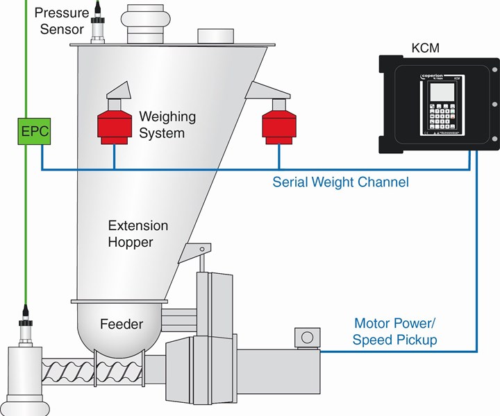
FIG 5 Function principle of the Electronic Pressure Compensation with sensors on both the hopper lid and the discharge
Using Vibration for Poorly Flowing Materials
In the case of LIW feeders, external vibration—including use of standard vibrators on feeder hoppers—can cause interference with the LIW signal if the control system cannot filter out this vibration. Alternatively, there are some new control technologies available that utilize vibration applied to the hopper and include an external drive tied directly into the weight-system controls (see Fig 6). This drive operates at a variable frequency and amplitude based upon the weighing and control system detecting nonuniform material flow by weight. This realtime device activates the external vibration only when there is an upset in the LIW signal, such as in the case of ratholes or material bridges. This type of “smart” vibration device is also self-tuning, with the controller adjusting the frequency and amplitude to compensate for changes in the hopper fill level or material flow, thus preventing bridges or ratholes before they can form.
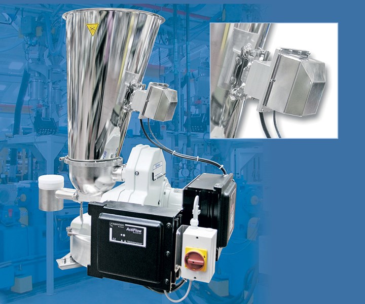
FIG 6 ActiFlow bulk solid activator is mounted outside the product zone and has minimal space requirements.
Todays’ advanced feeder controllers and load-cell technologies serve to improve not only feeder performance but also that of the overall process. Using these capabilities, processors can predict and prevent unplanned downtime, while also optimizing feeder effectiveness and maintenance requirements. It is important when evaluating a LIW feeder that close attention be paid to the overall connectivity, as well as reactivity of both the load cells and control systems, and any possible options for control upgrades. The investment made in a feeder that cannot only trend process parameters but also react quickly to influences of the process environment will result in a more robust feeding system.
About the Author: John Winski is dir. of sales for Coperion K-Tron, Sewell, N.J., where he is responsible for sales in the Americas of feeders, pneumatic conveying and engineered systems. He has 32 years of experience at Coperion K-Tron and has held positions as a service engineer, project engineer and regional sales management. He holds a degree in Electronics Engineering Technology from Temple University. Contact: (856) 589-0500 jwinski@coperionktron.com; coperion.com.


Related Content

Novel System Produces Color on Demand
Ampacet’s FluxQF technology features a quick-dispersion universal carrier with novel machinery that provides automated color blending in quantities down to 50 lb.
Read More
High-Performance, Cost-Effective Volumetric Feeder
New unit can handle a wide range of materials in various forms.
Read More
Solutions for Metal Contaminants in Plastic Feed Streams
At K Show 2022, Bunting will present technology for separating metal from recycled plastic feed.
Read More
Automated Resin Management and Blending System for Tight Spaces
NPE2024: Designed for new and existing operations with up to 10 machines and limited available space.
Read MoreRead Next

Understanding Low-Rate Feeding for Continuous and Batch Processes
Molders and extruders that need to feed tiny amounts of material to their process require precision in both the material being fed and the equipment doing the dosing. When a shot size consists of three pellets, there is no margin for error.
Read More
How to Troubleshoot Your Feeder to Achieve Optimal Performance
Even the tiniest improvements in compounding feeder accuracy can improve profits. Here’s how to keep your feeding system in the pink.
Read More
Optimize Feeding to Get More Money in Twin-Screw Compounding
Follow these practical examples to improve the feeding efficiency and productivity of your process.
Read More