
The Three Causes of Screw Wear
You run the risk of wasting time and money by not understanding what’s causing your screws to wear.
.jpg;width=70;height=70;mode=crop;format=webp)


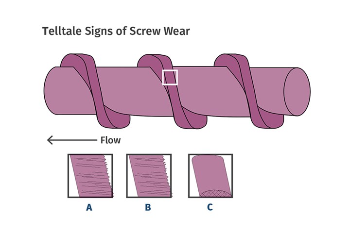
There are three main causes of screw wear in extruders. The first is the effect of unbalanced high-pressure areas in the screw, which are due primarily to screw design. The second is barrel alignment, typically the most destructive. The third cause of screw wear is use of abrasive fillers. Generally, the cause can be determined by examining the wear pattern on the flights (see illustration).
With respect to the first cause, the screw should be designed so that melt begins to form before compression starts. There should be enough melt present throughout the remainder of the screw to prevent complete solids plugging. If the design is too aggressive—i.e., too high a compression rate—melt can be forced downstream (or even upstream), leaving a short section of the channel filling completely with solids. In that case, the pressure at that point can instantaneously increase to extreme levels as the screw tries to force the solids downstream in an ever-decreasing area. I’ve observed instantaneous pressures exceeding 10,000 psi as a screw temporarily plugs with solids.


The plugging occurs only for a split second, during which the localized extreme shear stress over the plug temporarily relieves the plug by forming some melt. These plugs can form randomly and continuously over the whole compression length. Since the channel is eight to nine times the width of the flight, the pressure on the immediate leading and following flight can approach 4 to 4.5 times the pressure in the channel. With a much lower pressure on the opposite side of the screw, the screw is pushed with enormous force into the barrel opposite that location. The compression and rotating force of the screw combine to gall the hard surfacing to the barrel liner, simply “tearing” the hard surfacing off the flight.
A barrel expands as it is heated, so a screw that is easily slipped in the barrel when cold may be wedged in there when hot.
As shown in “A” in the accompanying illustration, the telltale sign of this kind of wear is a lip of the hard surfacing extending off the back of the flight. It’s usually very ragged and sharp. This is hard surfacing that has been deformed by the compressive and shearing forces opposite the plug. This always occurs in an area of volumetric compression before much melt has formed and is usually relegated to a length of 3 to 6 flights.
As for severe wear due to alignment of the barrel, keep in mind that a barrel expands as it is heated, so a screw that is easily slipped in the barrel when cold may be wedged in there when hot. The screw drive end is held centered in the drive quill and if it is rotated in a barrel that does not remain straight when heated, there is again tremendous force applied to the flight O.D. as the screw must constantly bend to rotate.
The coefficient of expansion of heat-treated 4140 steel (the most common screw material) is 6.8 × 10⁻⁶ in./in. That might not seem like much, but a screw 200 in. long will increase in length by 0.435 in. at 320 F. If, for some reason, the barrel cannot expand in a straight line due to an issue with a downstream component or the barrel support(s), severe flight wear will develop instantly. If the operating personnel are extremely familiar with the operating torque of the extruder, they may notice a higher than normal drive overload that will disappear rather quickly (in a matter of hours) as the flights wear. The appearance of wear due to misalignment (see “B”) looks like that from too much compression but it extends over a much greater length and occurs in areas of no compression where a full melt exists, like near the screw tip.
The third cause of high wear is abrasive fillers. The typical radial clearance for screw-to-barrel is 1/100th of the diameter, so one might think particles smaller than that would not be a problem. Not true. Remember: The screw does not remain perfectly centered in the barrel over its full length; it moves constantly in that clearance due to varying pressure and torque. As a result, there is continuously moving contact of the screw flights with the barrel liner. This means very tiny particles that are harder than the screw flights will cause micro abrasions by being trapped between the rotating screw flight and barrel liner.
Most wear-resistant hard-surfacing materials used for screw flights get their wear resistance from various carbides or borides suspended in a nickel or cobalt matrix. Although these carbides and borides are extremely hard, the supporting matrix is much softer, and the abrasive fillers cause wear to the matrix by a million tiny scratches. Since the tiny scratches are mostly invisible without magnification, the worn flight surface will appear to be almost polished. The particles also tend to round the flight. The resulting polished and rounded surface is shown in “C.” This wear can cover a large portion of the screw flights, to a greater degree in the feed and compression sections where the loose fillers have not yet been incorporated into the melt.
Careful analysis of the flight wear can provide insight into the proper corrective actions. Often, enormous amounts of repair cost and machine downtime are wasted by not understanding the cause of the wear.
About the Author: Jim Frankland is a mechanical engineer who has been involved in all types of extrusion processing for more than 40 years. He is now president of Frankland Plastics Consulting LLC. Contact jim.frankland@comcast.net or (724) 651-9196.


Related Content

PBT and PET Polyester: The Difference Crystallinity Makes
To properly understand the differences in performance between PET and PBT we need to compare apples to apples—the semi-crystalline forms of each polymer.
Read More
Tunnel Gates for Mold Designers, Part 1
Of all the gate types, tunnel gates are the most misunderstood. Here’s what you need to know to choose the best design for your application.
Read More
How to Stop Flash
Flashing of a part can occur for several reasons—from variations in the process or material to tooling trouble.
Read More
Understanding Strain-Rate Sensitivity In Polymers
Material behavior is fundamentally determined by the equivalence of time and temperature. But that principle tends to be lost on processors and designers. Here’s some guidance.
Read MoreRead Next

New Injection Screw Breaks the Rules, But Fixes Many Molding Defects
“Revolutionary” screw design turns conventional plastication theory upside down.
Read More
Telltale Signs of Screw Wear
Determining the cause of wear is the first step in eliminating it.
Read More
EXTRUSION: The Two Main Causes of Screw Wear
Wedging and misalignment are often confused with each other when inspecting a worn screw.
Read More