
Tooling: How to Properly Size, Gates, Runners and Sprues, Part 2
Get the sprue, runner and gate sizes close to ideal the first time around.


Last month, I discussed the importance of proper gate depths and gate widths. This month, I will focus on two different types of gates, as well as gate land length, and gate-freeze time.
Sub-Gates
There are several different types of sub-gate shapes, as mentioned in my January 2018 article, Tunnel Gates for Mold Designers. The most common ones are conical because they are the least expensive to machine. “D”-shaped and chisel-shaped sub-gates are also very common.


To determine the size of a conical sub-gate, start by assuming the part was going to be edge gated. Using the guidelines discussed in last month’s column, estimate the gate depth and width. Multiply the depth times the width to get the flow area. Then convert this area into a diameter. That way, the sub-gate diameter has an area equivalent to an edge gate. The formula is:
Sub-Gate Diameter= √ (Edge Gate Depth × Width ÷ π) × 2
For conical or “D”-shaped gates, this diameter is the size of a gauge pin that can fit through the hole. It is the minor diameter of the elliptical sub-gate scar. It is not the major diameter of the ellipse, nor the entire area of the ellipse, or “D” shape. If you think about it, this is similar to comparing the flow area of a full-round runner to a trapezoidal, parabolic, or any other runner shape.
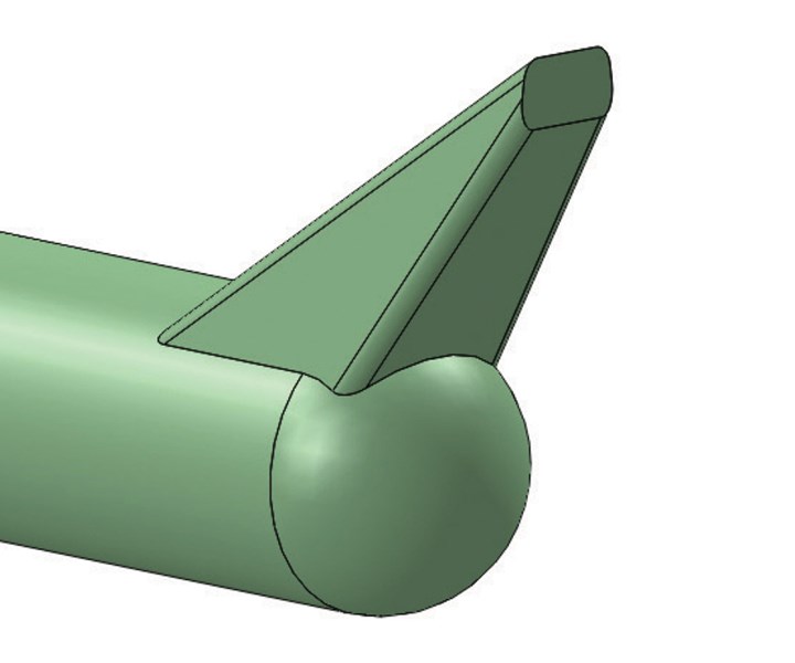 FIG 1 A chisel-shaped sub-gate.
While conical and “D”-shaped sub-gates are the most common, they are the least desirable. You cannot control the gate-freeze time and material flow rate through the gate independently. If you have a long flow length, the sub-gate would need to be larger to fill the cavity. This causes the gate-freeze time to be needlessly longer. The preferred type of sub-gate is chisel shaped, as in Fig. 1. The gate depth and width you want for a chisel-shaped sub-gate are the same dimensions you would use for an edge gate. This allows you to control the gate-freeze time and the flow length independently without having to extend the cycle time. Another advantage to the chisel sub-gate is that it leaves a smaller gate vestige than a conical sub-gate, especially when the gate is located on a wall that has a steep taper or a radiused surface. It also has less chance of producing mold-damaging flakes.
Direct Sprue Gates
Direct sprue gating is used in single-cavity molds. There is no runner or a conventional gate. The sprue-bushing orifice on a direct-gated part is effectively the gate. The sprue-bushing orifice size is one of the least understood dimensions in mold designs—especially with direct-gated parts.
The sprue-bushing orifice on a direct-gated part is effectively the gate.
Sizing a direct sprue-gated part can be a difficult challenge. Ideally, you want the outlet diameter of the sprue bushing where it meets the part to be about 1.5 times the wall thickness of the part. For example, if the part had a wall thickness of 0.100 in., the outlet diameter of the sprue bushing would be about 0.150 in. If it is much larger than that, it will cause the cycle time to be extended, because the pack pressure and hold time must be high enough and long enough to prevent a sink mark on the opposing surface of the part. It can also be a challenge to prevent blush on the surface—especially since direct-gated parts usually don’t have a cold well to catch and retain a cold slug from the machine-nozzle tip.
When considering what the inlet, or “O”-orifice diameter should be, I start by considering what size would I use if the part were edge gated, just like I did in the previous sub-gate example. That makes it easy to determine what the minimum orifice size should be. Let’s assume that if the part were edge gated the gate would be 0.050 in. deep × 0.200 in. wide. The flow area is therefore equal to 0.050 in. × 0.200 in. = 0.100 in2. An equivalent diameter would therefore be the square root of (0.100 ÷ π) × 2 = 0.113 in.
So now we know the “ideal” inlet and outlet diameters of the sprue bushing for this direct sprue-gated part. Achieving these values is going to be based on the length and internal taper of the sprue bushing—and that’s where things get challenging, if not impossible. In this example, to have an inlet or “O” diameter of 0.113 in. and an outlet diameter of 0.150 in. a sprue bushing with an industry-standard internal taper of ½ in./ft (2.386° included) would only be about 0.89-in. long. That’s probably not going to be long enough to go from the face of the injection clamp plate all the way down to the part. You can often minimize the overall length of the sprue bushing by counter-boring the clamp plate and sometimes a portion of the cavity plate.
I once mounted the underside of the head of a sprue bushing directly against the back of a cavity insert. The nozzle contact pressure from the machine’s barrel was strong enough to snap the bolts and push the cavity insert out of its pocket and onto the floor. The larger the machine, the larger the nozzle contact force. Therefore, if you go this route, select the size and quantity of bolts retaining the insert with this in mind.
You can also make a custom sprue bushing and reduce the internal taper from the standard 2.38° included, to just 1° to 2° included. Base your decision on what angle you think you can get away with on the thickness of the sprue and the shrinkage rate of the material. The best way to make a custom sprue bushing is to buy a stock sprue bushing with a smaller “O” dimension. The smaller orifice becomes the starter hole for wire EDM-ing the bore to the desired size and taper.
You don’t want to reduce or increase the sprue’s estimated “O” dimension, which controls the required injection pressure and the gate-freeze time. If the length is a problem, the only thing you can do is live with a larger outlet diameter. In order to minimize the increase in cycle time, the sprue bushing needs direct cooling. Indirect cooling via water channels near the sprue bushing is usually not very effective—unless the sprue is cut directly into the cavity insert, meaning there is no separate sprue bushing. Using a sprue bushing made of a copper alloy, or one that is conformally cooled, will be very helpful.
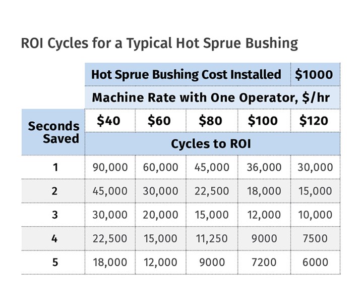
Unfortunately, many direct sprue-gated parts are inject/eject on the same side (reverse ejected), and the sprue bushing is extremely long. The best solution in a case like this is to consider using a hot bushing. If you think that the cost of a hot sprue bushing is prohibitive, the accompanying table details the number of cycles it takes to recoup their average cost. The ROI is based on the hourly machine rate and the expected cycle-time savings. Once you reach the ROI cycle quantity, the profit on the molded part increases from there on in.
These are conservative numbers because they do not factor in the material saved and the possibility of reducing the labor requirements. It also doesn’t factor in the reduced scrap rate. Try to order hot sprue bushings that leave a small cold sprue and have a replaceable tip. That way you can buy tips of different length to put the same bushing in different molds for even more savings. Lastly, whether you have a cold sprue or a hot sprue bushing, add a 0.005-in. to 0.025-in. radius at the outlet of the bushing. Thermoplastics don’t like sharp corners of any kind.
Edge-Gate Land Length
In order to discuss edge gates, we need to first discuss land length. The land length for an edge gate is a short straight section connecting the outer surface of the part to the runner, as shown in Fig. 2. A gate’s land length has a direct effect on the viscosity of the material. Longer lands impart more shear to the material, which in turn reduces the material viscosity. That can be beneficial, if not necessary, to help improve the flow length into the cavity. Long land lengths can also be detrimental and create burns with shear-sensitive materials, such as PVC.
A gate’s land length has a direct effect on material viscosity.
The longer the land length, the greater the pressure required to push the material through the gate—like breathing through a long straw versus a short straw. However, since long lands reduce the viscosity of the material, it takes less pressure to fill the cavities—especially at high injection velocities.
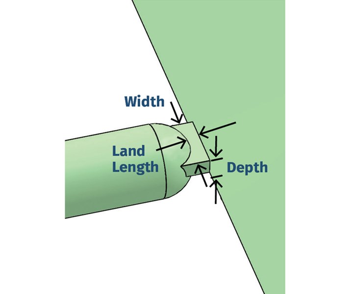 FIG 2 Edge-gate terminology.
There is an old rule of thumb that says the gate land length should be half the depth of the gate. This is yet another “rule” that you would be wise to forget. I have seen molds with zero gate land, and I have seen molds with land lengths over 1½ in. Both worked just fine for their particular application. The general consensus among industry experts is that a gate’s land length should be between 0.020 in. and 0.045 in. That’s a pretty good general rule, but rules always have some exceptions, which unfortunately are rarely mentioned.
Your decision on how long to make the gate land should be based on the expected injection velocity. If you are going to inject extremely fast, such as with a thin-walled part having a shallow gate depth, a short land length is usually necessary. If you are going to inject extremely slowly, such as with a thick-walled part having a very deep gate, the land length can be considerably longer, because there is very little pressure loss going through that gate. The ideal land length is also somewhat material dependent. Always review the material manufacturer’s design guidelines, but keep in mind that most design guides are general in nature.
It is always best to start with a slightly longer gate land. If there is an issue with either high shear or high injection pressure going through the gate, it is steel-safe and you can reduce it. Don’t make the molder have to process around an incorrectly sized gate. The resulting processing window will be narrow and the likelihood of rejects will increase exponentially. Whatever you do, just make sure all of the gates in a multi-cavity mold have the exact same gate depth, width and land length. Otherwise, you will get a cavity imbalance.
Gate Freeze
In May 2000, Bill Fierens ( now sr. technical development engineer at M. Holland Co.) and Sean Mertes ( now application development engineer at Amco Polymer) presented a paper at the SPE ANTEC on “Gate Land and its Effects on Gate/Cavity Pressure Loss.” The paper briefly asserted that short lands can increase the gate-freeze time. I spoke with both authors, and while there is no empirical data to support this statement, we all believe it to be true for two primary reasons. First, short lands have less steel in the gate area, and area is a primary variable in the mathematical equation for calculating the rate of heat transfer by conduction. Second, the shorter the land length, the closer the runner is to the gate—putting additional heat into this critical area. Additionally, if the wall of the molded part is thick, it also puts additional heat into the critical area. As mentioned before, thick-walled parts or parts with large round runners can require longer lands.
While I am certain that a gate with a 1-in. land will solidify faster than a gate with a 0.100-in. land, I find it difficult to believe that there would be much of a difference in the solidification time between a gate with, say, a 0.020-in. land and one with 0.045-in. land. Additionally, since shorter lands develop less shear, there will be less temperature rise in both the material and the steel. If the gate-freeze time is in fact extending the molding cycle, I think it is more likely that it’s not because the land is too short—it’s because the gate is too deep. Without empirical data, we will never know for sure.
This brings up another point worth mentioning. Companies that have adopted scientific molding methods perform gate-freeze studies on their molds. John Bozzelli’s November 2015 column, entitled “Gate-Seal Testing Done Right,” is a thorough guide on how to perform this study. Basically, you start with a very short second-stage hold time—about 1 sec, and then weigh the part(s). You then incrementally increase the hold time while maintaining the cycle time, until the part weight no longer increases. Now you know how long it takes for the gate to freeze, which prevents material from flowing backwards into the runner, causing the part to be underpacked. If you want to use a “gate unfreeze” condition, you still need to perform this study in order to know how much less hold time to use. Either way, you know how long the hold time needs to be before starting screw rotation.
Always perform a gate-freeze study.
What a gate freeze-study doesn’t tell you is whether the gate is too shallow or too deep. It also doesn’t tell you if the land is too long or too short. The part, the molding machine, and physical testing will tell you those things. If the part still has visible sink marks or internal voids, or is dimensionally undersized after the gate has frozen, the gate depth probably needs to be increased. This will increase the gate-freeze time, which is necessary in order to pack more plastic into the cavity. As I just mentioned, if it takes a long time for the gate to freeze, the gate is probably too deep. But it is also possible that the hold pressure is too high and semi-solidified material in the gate is continually pushed into the cavity. If the pressure loss going through the gate is extremely high or the material is jetting into the cavity, the gate could be too shallow or the land too long.
ABOUT THE AUTHOR: Jim Fattori is a third-generation injection molder with more than 40 years of experience in engineering and project management for custom and captive molders. He is the founder of Injection Mold Consulting LLC, an international consulting company. Contact: jim@injectionmoldconsulting.com; injectionmoldconsulting.com.


Related Content

Tunnel Gates for Mold Designers, Part 1
Of all the gate types, tunnel gates are the most misunderstood. Here’s what you need to know to choose the best design for your application.
Read More
Back to Basics on Mold Venting (Part 1)
Here’s what you need to know to improve the quality of your parts and to protect your molds.
Read More
Why Shoulder Bolts Are Too Important to Ignore (Part 1)
These humble but essential fasteners used in injection molds are known by various names and used for a number of purposes.
Read More
How to Start a Hot-Runner Mold That Has No Tip Insulators
Here's a method to assist with efficient dark-to-light color changes on hot-runner systems that are hot-tipped.
Read MoreRead Next

Part 1: How to Properly Size Gates, Runners and Sprues
Get the sprue, runner and gate sizes close to ideal the first time around—without spending a lot of time on extremely complicated formulas.
Read More
Tunnel Gates for Mold Designers, Part 1
Of all the gate types, tunnel gates are the most misunderstood. Here’s what you need to know to choose the best design for your application.
Read More
How Polymer Melts in Single-Screw Extruders
Understanding how polymer melts in a single-screw extruder could help you optimize your screw design to eliminate defect-causing solid polymer fragments.
Read More