
Tooling: How to Properly Size, Gates, Runners and Sprues, Part 3
Get the sprue, runner and gate sizes close to ideal the first time around.


Part one of this series (March ‘20) discussed the importance of proper gate depths and gate widths. Part two (April ‘20) discussed two different types of gates, gate land length, and gate-freeze time. This month I will discuss edge gates and runner sizes.
Edge Gates
Figure 1 depicts a simple edge gate. It is the most commonly used gate type—probably because it is the least expensive to machine. All that is required is an end mill to connect the cavity to the runner. This type of gate is also the easiest to measure its depth, which is critical in multi-cavity molds. However, this design has several shortcomings.


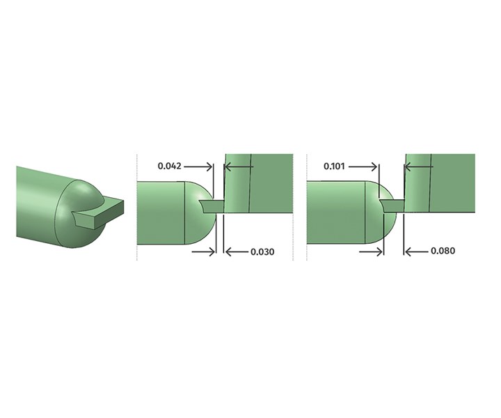
FIG 1 Land lengths of a basic edge-gate design.
One of them is the land-length variation. The land length in Fig. 1 is 0.030 in. on the bottom of the gate and 0.042 in. on the top. This is due to the gate being machined into just the cavity side of the mold, and the runner being full round. Ideally, an equal gate depth should be cut into both the cavity and core sides, so that the material enters the cavity from the very center of the melt stream. But this is not often possible due to the part geometry in most two-plate molds. Notice how these differences in land length are only in the center of the gate. There is a considerably greater difference as you approach the outer edges—almost three times longer in this example. There is also a realistic concern that the small amount of steel between the center of the runner and the cavity, which is equal to the land length, may not be sufficient to protect the mold from damage due to high injection pressures, or in the event of flashing.
Figure 2 depicts a chisel-type edge gate, so called because it is shaped like a wood chisel. This example has a 0.030-in. land length on the bottom and zero land length on the top, where it starts to taper out to join the runner. Zero land length is both ideal and impractical. It’s ideal because it provides the lowest pressure loss through the gate, and it is the easiest to trim precisely with a gate cutter or robotic nipper. It’s impractical because even if the mold is made of-heat treated tool steel, the razor-sharp edge on the cavity wall will wear prematurely, especially if the material is abrasive. The steeper the angle, the faster and deeper it will wear.
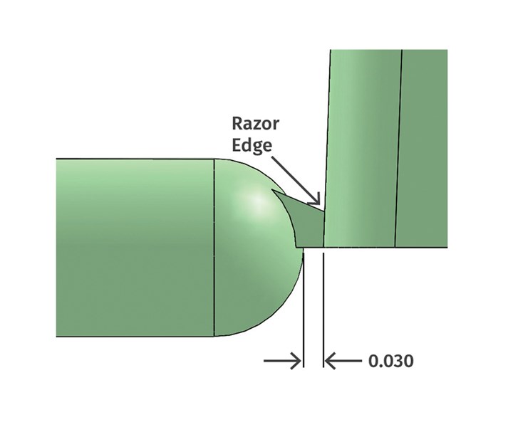
FIG 2 Razor edge on a chisel-type edge gate.
Figure 3 depicts an improved tapered edge-gate design. It has the same 0.030-in. land length as the previous examples, and then tapers out in three directions. The intersection of the tapered portions and the runner have generous radii. There is also a 5° taper on the sides to facilitate release from the cavity. This design provides a sufficient amount of steel between the runner and the part. There is a uniform land length on both the top and bottom, and from the center to the outer edges. The gate depth is easy to measure. The material flow from the runner to the gate is less restrictive, and there is less shear sensitivity due to the elimination of the sharp edges. This design is obviously more time-consuming to machine using an EDM electrode and then hand blending the intersections, but its benefits often outweigh the cost.
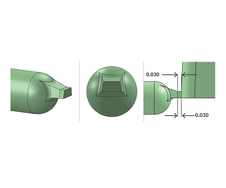
FIG 3 Improved edge-gate design.
These same improved edge-gate design can be applied to a very wide gate, such as a fan gate, as shown in Fig. 4.
Determining the Runner Sizes
The goal of sizing a runner is similar to that of sizing a gate. You don’t want the runner to be too small or too large. If it is too small it requires a lot more pressure to fill the cavities, and there is a chance it will freeze off before the part is fully packed out. Even if reground material is allowed, you still don’t want the runner too be too large, because it can extend the cycle time. Determining the size of a runner, just like a gate, is a balancing act. To properly size a runner, you have to start at the gate end and work your way back toward the sprue.
Determining the size of a runner is a balancing act.
Have you ever heard the real-estate catch phrase: location, location, location? For two-plate injection molds, the runner-system catch phrase is: full round, full round, full round. While full round, trapezoidal, parabolic and square runners have the largest ratio of cross-sectional area to peripheral, or surface length, as compared with all other runner shapes, a full-round runner provides the least amount of shear. It solidifies quickly and more uniformly when compared with other runner shapes. And it provides the best melt conditions—especially for edge gates—because the material entering the cavity will be near the center of the melt stream.
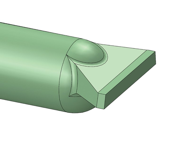
FIG 4 Improved wide edge-gate design.
Most of us have been taught that runner branches in a cold-runner system should vary in diameter, as opposed to having a constant or uniform diameter. The runner branch feeding the gate would be the smallest. The subsequent branches would get progressively larger, leading up to the primary runner and sprue. This varying or graduated-diameter runner requires less pressure to fill a part than a constant or uniform-diameter runner does. However, a varying-diameter runner can have a longer cycle time than a constant-diameter runner because the larger primary runner branch takes longer to cool.
If the material is fairly viscous, such as rigid PVC, a varying-diameter runner is typically the best way to go, so as not to have a significant pressure loss and elevated shear stress. But if the material has a low viscosity, such as polyethylene, and the fill pressure is not an issue but the packing pressure is, a constant-diameter runner is often the better choice, because it will set up faster. While others may disagree, my personal preference is to use a varying-diameter runner regardless of the material type. I prefer to minimize the fill pressure and shear stress as much as possible. If the large primary runner extends the cycle time, I simply add some stiffening ribs, which also act as flash traps, and some gussets connecting the primary runner to both the sprue and the cold well, as depicted in Fig. 5. This intersection, regardless of the runner type, is almost always the most massive, which takes the longest to reach its ejection temperature.
Just so we are all speaking the same language, the hierarchy of runner sizes is primary, secondary, tertiary, quaternary and quinary. These are typical in naturally balanced two-, four-, eight-, 16- and 32-cavity molds. If you have more cavities than that, the next levels are senary, septenary, octonary, nonary and denary. Note: This same terminology also applies to the flow channels in a hot-runner system.
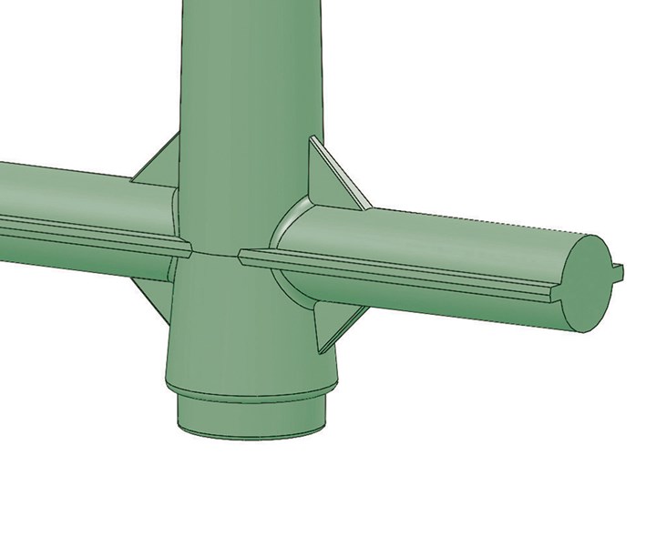
FIG 5 Sprue and runner with gussets and stiffening ribs.
The diameter of the runner feeding the gate is extremely critical for two reasons. First, it has a significant effect on the processing window and the part quality. Second, because the size of the other runner branches in a varying-diameter system are directly related. A good starting point is to make the last runner diameter 1.5 times the wall thickness of the part where it is gated into. This may seem like an overly simplistic rule, which it actually is, but the alternative is to perform some intricate empirical calculations, or to perform a flow analysis. For the average custom molder, the time and cost factors for either of those approaches is often not warranted or achievable.
The diameter of the runner feeding the gate is extremely critical.
Since rules always have exceptions, a 2004 study determined that it is often possible to use smaller runner diameters—equal to, or possibly even smaller than, the wall thickness of the part. It depends on the part’s wall thickness, the type of molding material, the injection flow rate, and the resulting shear rates. If you are trying to shave seconds or minimize virgin material costs, there’s certainly no harm in starting off with smaller runner diameters, since they are steel safe and can be enlarged if needed after the initial mold sampling.
Do not make the runner diameter 1.5 times that of a thicker wall section located somewhere else on the part. Packing out that section is based on the wall thickness between the gate and that section. A larger runner diameter will not help pack out that section. As most of you know, one of the golden rules in our industry is to always try to gate into the thickest section of a part. Unfortunately, the part design, the aesthetic requirements, and the gate-stress considerations often require the gate to be located in a less-than-ideal location.
Following the 1.5 times guideline, if a part has a wall thickness of 0.100 in., the last runner diameter should be approximately 0.150 in. diam. Even though today’s CNC machines can cut any size desired, it is better to use a standard cutter size to reduce the machining time. Therefore, round this 0.150 in. up or down to the next standard cutter size—in increments of 1/64 in. The next step is to adjust this diameter to compensate for four variables: shot weight (parts and runner), runner branch length, material viscosity and shear sensitivity. I must point out that these adjustments usually do not need to be made if you have a very thick-walled part, with a very deep gate, and therefore, a very large runner feeding the gate. That is a unique situation where these four variable have very little effect.
Adjust the runner diameter to compensate for shot weight, runner length, viscosity and shear sensitivity.
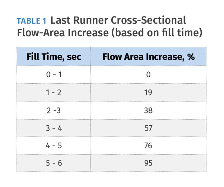
Molds with large shot weights or shot volume typically have longer fill times. During the filling phase, the exterior of the runner starts to solidify against the cold surface of the mold and the effective flow area gets smaller and smaller. The runner diameter must be adjusted accordingly. Despite my disdain for rules of thumb, the following guidelines are recommended: Increase the cross-sectional flow area of the runner, not its diameter, by 19% for each second of fill time greater than one, as shown in Table 1. If the runner diameter gets extremely large, it is an indication that a second gate and runner branch may be required. Why? As discussed last month, if you double the number of gates, the flow rate (in.3/sec) and the flow speed (mph) gets cut in half. Now you can double your injection velocity, which cuts the fill time in half, and maintains the same melt viscosity entering the cavity.
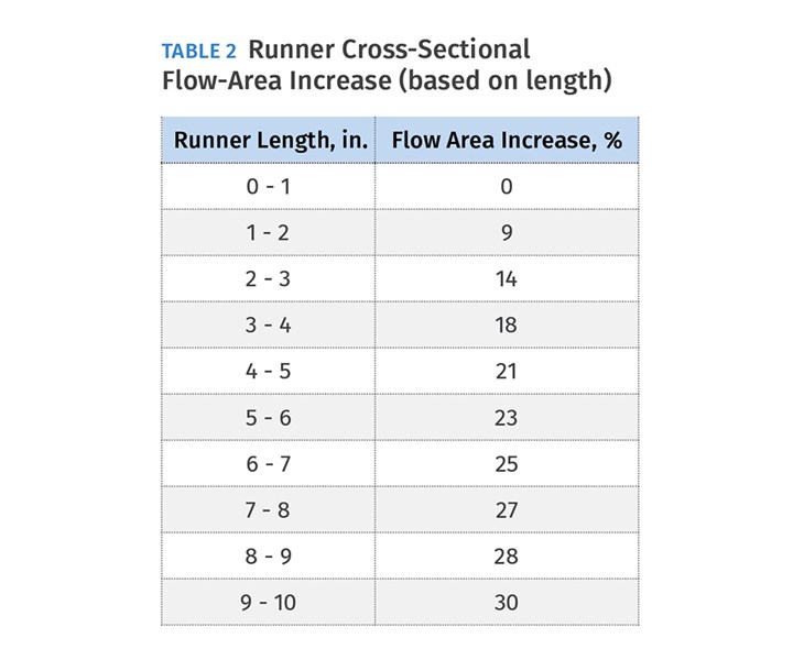
The next adjustment is to factor in the runner’s length. As the length of the runner branch increases, so does the material’s resistance to flow. Once again, increase the cross-sectional flow area, not the diameter, by the percentages shown in Table 2.
The last runner-branch adjustment is to factor in the material’s viscosity and shear sensitivity. Unless you know your way around a plot of viscosity versus shear rate, this adjustment will be based primarily on experience. Do not increase the flow area for low-viscosity materials, such as semicrystalline PE, PP or PA (nylon). For medium-viscosity amorphous materials, such as PS, ABS and SAN, add 10% to the flow area. For high-viscosity materials, such as PMMA (acrylic) and PVC, increase the flow area by 20%.
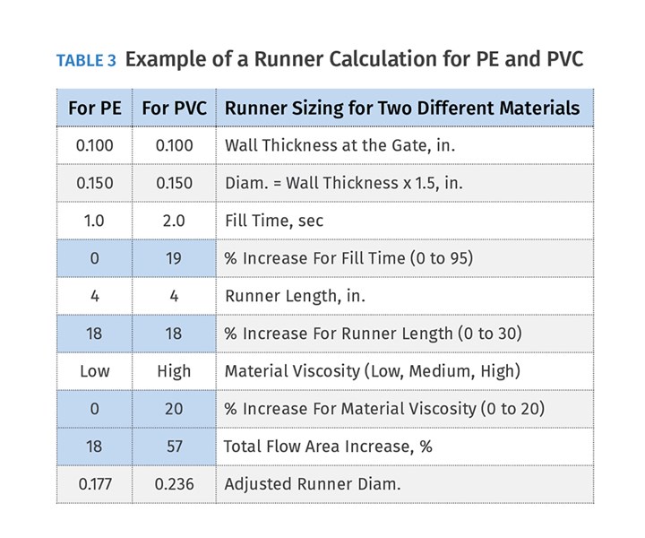
Putting this all together, a good approximation of the diameter of the runner branch feeding the gate is equal to the part’s wall thickness x 1.5 + an adjustment for the fill time (0 to 95%) + an adjustment for the branch length (0 to 30%) + an adjustment for the material viscosity (0 to 20%). Table 3 shows an example of this calculation for a mold running both polyethylene and rigid PVC. In this example, they both have the same part wall thickness of 0.100 in. and the same runner length of 4 in. The only differences are the fill time and the material viscosity. As a result, the adjusted runner diameter feeding the gate would be 0.177 in. for PE, or 0.236 in. for PVC.
Once you have determined the diameter of the runner feeding the gate, calculating the sizes of the remaining runners leading up to the sprue is much simpler. Some people say that the cross-sectional flow areas of these runners should be equal to the combined flow areas of the branch runners it feeds. That’s another terrible rule of thumb, because it will result in excessively large runners. The correct formula for calculating the remaining runner diameters is:
Dfeed = Dbranch x N1/3,
where Dfeed is the diameter of the runner feeding the branch, Dbranch is the diameter of the runner branches, and N is the number of runner branches (typically two and occasionally four for geometrically balanced runner designs.) There is no need to adjust these diameters for fill time or material viscosity. You already accounted for them when determining the runner diameter feeding the gate. However, common sense will dictate whether an adjustment should be made to account for any long runner lengths.
Let’s do an example using these guidelines: Figure 6 depicts an eight-cavity mold with primary, secondary and tertiary runner branches. The material is PE, the fill time is less than 1 sec, and the wall thickness of the part at the gate is 0.100 in. The length of the tertiary runner section is 1.0 in. long. Therefore, the tertiary runner feeding the gate should have a diameter of 0.100 x 1.5 = 0.150 in. No other adjustments need to be made in this case.
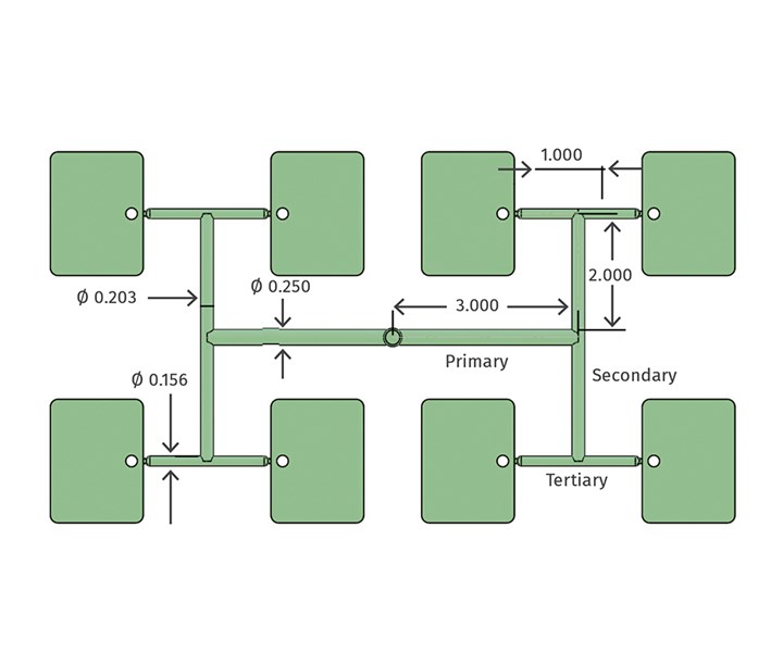
FIG 6 Examples of runner sizes.
Let’s round this value up or down based on a standard cutter size—in this case 5/32 or 0.156 in. The diameter of the secondary runner would be the diameter of the tertiary runner times the number of branches to the 1/3 power (cube root). In this case it would be 0.156 x 21/3 = 0.156 x 1.26 = 0.197 in. Again, you would round this value up or down based on a standard cutter size, which is 13/64 or 0.203 in. That works out to an 83% increase in flow area—not twice the flow area, as others might suggest. The primary runner should follow the same sizing formula. Therefore, it should be 0.203 x 21/3 = 0.256, rounded down to ¼ in. diam.
That works out to a 52% increase in flow area—considerably less than twice the flow area—and that makes sense. Since plastic has an extremely low coefficient of thermal conductivity, it insulates itself. The larger the runner diameter, the larger the percentage of molten material will be in the center. Therefore, the amount of pressure loss and the amount the cross-sectional flow area needs to be increased is not linear.
About the Author: Jim Fattori is a third-generation molder with more than 40 years of experience in engineering and project management for custom and captive molders. He is the founder of Injection Mold Consulting LLC in Pennsylvania. Contact: jim@injectionmoldconsulting.com;
injectionmoldconsulting.com


Related Content

How to Get Rid of Bubbles in Injection Molding
First find out if they are the result of trapped gas or a vacuum void. Then follow these steps to get rid of them.
Read More
Best Methods of Molding Undercuts
Producing plastics parts with undercuts presents distinct challenges for molders.
Read More
Know Your Options in Injection Machine Nozzles
Improvements in nozzle design in recent years overcome some of the limitations of previous filter, mixing, and shut-off nozzles.
Read More
Improve The Cooling Performance Of Your Molds
Need to figure out your mold-cooling energy requirements for the various polymers you run? What about sizing cooling circuits so they provide adequate cooling capacity? Learn the tricks of the trade here.
Read MoreRead Next

Part 1: How to Properly Size Gates, Runners and Sprues
Get the sprue, runner and gate sizes close to ideal the first time around—without spending a lot of time on extremely complicated formulas.
Read More
Tooling: How to Properly Size, Gates, Runners and Sprues, Part 2
Get the sprue, runner and gate sizes close to ideal the first time around.
Read More