
Tooling: How to Properly Size Gates, Runners and Sprues; Part 5 of 5
Get the sprue, runner and gate sizes close to ideal the first time around.


This month I sifted through four decades of Post-It notes, hand sketches and photographs to uncover a number of worthwhile tips and tricks related to this five-part series on gates, runners and sprues. Therefore, this month’s conclusion to the series will simply be a bullet-point list of helpful information.
Runners
• Full-round, parabolic and trapezoidal are the only three types of runners to be used in an injection mold—in that order.


• Always use geometrically (or “naturally”) balanced multi-cavity runner layouts. Multi-cavity molds inherently have balancing issues. Don’t compound the problem with fishbone, ladder, or other types of unbalanced runner designs.
• Some runner layouts can have a heavy mass at branch intersections. These can often be cored out without affecting the material flow or pressure, as shown in Fig. 1.
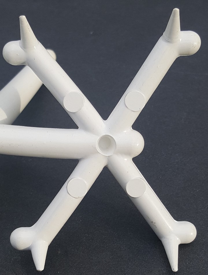
FIG 1 A cored-out runner intersection.
• One clever engineer engraved text on a family-mold runner to help the operators identify similar-looking parts for sorting and assembly, as shown in Fig. 2. Engraving the cavity number on the runner is also helpful when the parts are very small or the aesthetic requirements do not allow a cavity number on the part.
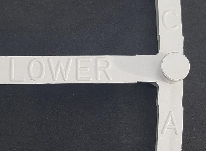
FIG 2 An engraved runner.
• Never machine a runner on a split line of two or more mold inserts. The injection pressure will try to push the components apart, resulting in “down-flash” that could cause the runner to stick.
• Designing the mold with a separate runner bar or runner block will cost a little more but has multiple benefits—especially for long running molds.
1. Any size adjustments to the runner are faster and easier to machine.
2. It can be easier to put a cooling channel in the insert on a separate circuit, which can help reduce the cycle time.
3. In the event of parting-line flash, the runner inserts can be skim ground and shimmed up This eliminates the need to make any other height adjustments to the cavities, interlocks, cams or shutoffs.
4. The inserts can affordably be made of a different material, such as a high-hardness tool steel for abrasive materials, or thermally conductive materials for faster cycles.
• Flash traps are beneficial in any cold-runner system, whether it it’s a two-plate, three-plate, or stripper-plate mold.
• Add a runner overflow at each runner intersection. This is particularly important for stripper-plate molds when there is no cold well opposite the sprue. The length of the overflow should be 1.0 to 1.5 times the runner diameter or width. Overflows work very well, as shown in Fig. 3.
FIG 3 Proof that overflows work.
• Figure 4 shows two different runner designs. Both runners have sub-gates machined into the injection half of a two-cavity mold. The runner on the left is far superior to the one on the right because:
- 1. The cold well is large enough to catch and retain any cold slugs from the machine nozzle tip.
- 2. The gussets help pull the sprue out of the bushing without detaching from the runner. Otherwise, the cycle time is increased until the massive intersection is sufficiently solidified.
- 3. There are no pullers directly under the sub-gates, which would prevent them from flexing when the mold opens. If the sub-gate didn’t flex, it could break off, or produce flakes.
- 4. The sub-gates feed off the side of the runner, allowing for a small overflow, and a good location to add a runner vent.
- 5. The sub-gates are chisel-shaped. They allow adjustments to the width and the depth, like an edge gate does—independently controlling either the flow speed or the gate-freeze time.
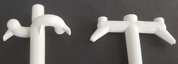
FIG 4 A really good, and a not so good, runner design.
• For shear sensitive or glass-filled materials, radiused runner turns are preferred over 90° bends.
• “Breaking” or blending the sharp edges of the runner system will help reduce stress on the material and help prevent the runner from cracking upon ejection. Sharp edges are typically located where the sprue meets the runner, where the cold well meets the runner, where the gate meets the runner, and at every runner intersection.
Gates
• It is best to edge gate parts from a full-round runner.
• Sub-gates can be fed from a full-round, parabolic or trapezoidal runner.
• For high-volume molds (about 500,000 cycles or more), consider incorporating replaceable gate inserts, especially for abrasive materials.
• Avoid using sub-gates if the molding material is abrasive, or if the cavity is made of a soft metal, such as aluminum or copper. They will wear out quickly.
• Sub-gates do not necessarily have to be machined parallel or perpendicular to the runner. They can be machined on almost any angle. This is helpful when gating into a part with a radius or a steep angle, or when you want to shift a weld-line location.
• An edge gate or sub-gate that intentionally feeds a part on an angle is referred to as tangential gate, as shown in Fig. 5. It is often used to prevent core shifting, relocate a weld line, or improve weld strength. However, it can cause jetting inside the cavity.
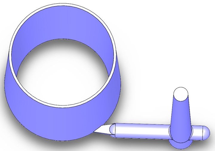
FIG 5 A tangentially gated part.
• Keep in mind what effect the gate location and runner pattern will have on the mold. The gate and runner in Fig. 6 may be a balanced design, but it caused the cavity and core halves of the mold to rotate in opposite directions, resulting in parts that had a core-shift problem.
FIG 6 A bad gate-location design.
Balancing Family Molds
• The goal in balancing a family mold is to have all of the parts finish filling at the same time—not start to fill at the same time. Keep that in mind when you are making progressive short shots.
• One reason you want all of the parts in a family mold to finish filling at the same time is so they all receive the same amount of packing pressure. If they don’t, you waste material by over-packing some cavities, which makes them heavier. Another reason is that cavities that are under-packed or over-packed will have dimensional issues because they will have a different shrinkage rate than what was used to machine the mold.
• The trick to adjusting a family mold is to adjust the flow rate of the material in the runners feeding each cavity. Changing the gate depth or width only changes the fill speed (mph). It does not change the flow rate (in.3/sec). Changing the gate depth will also create different gate-seal times, which leads to parts having different packing pressures. Therefore, to correctly balance family molds, change the runner diameters to each cavity, as shown in Fig. 7.
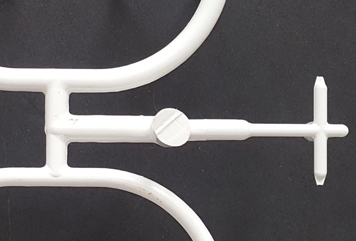
FIG 7 A runner with varying diameters.
• If you want to increase the size of the gates, runner or sprue by some percentage, you need to run the numbers. For example, if you feel a 0.050-in. gate should be about 20% larger, don’t multiply the gate size by 1.2 and get 0.060 in. That’s not 20% larger. In terms of flow area, that’s 44% larger. An easy and correct way to determine the new gate is size is to use the following formula: DNEW = DEXISTING × √ (1 + percentage increase). In this case, it would be 0.050 × √ 1.2 = 0.055.
• Adding a short flow restrictor, as shown in Fig. 8, is not as effective as reducing the diameter of the entire runner branch.
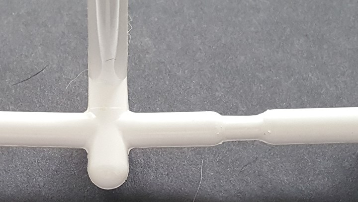
FIG 8 A runner with a short flow restrictor.
• Adding redundant runner sections, as shown in Fig. 9, has only a minor effect on cavity balance. They will also narrow the processing window and increase the amount of runner scrap or regrind.
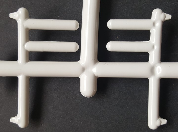
FIG 9 A runner with redundant branches.
Ejection
• Ejector pins should be flush with the bottom of the runner. They should never enter into the flow channel.
• A shortened ejector pin is required for ejecting a runner puller near a sub-gate machined into the cavity side. A good puller design is shown in Fig. 10. Note how the ejector pin has a smaller diameter than the puller and how the puller has a radius and small pad on the bottom. This design will minimize the risk of getting flakes or shavings on the parting line.
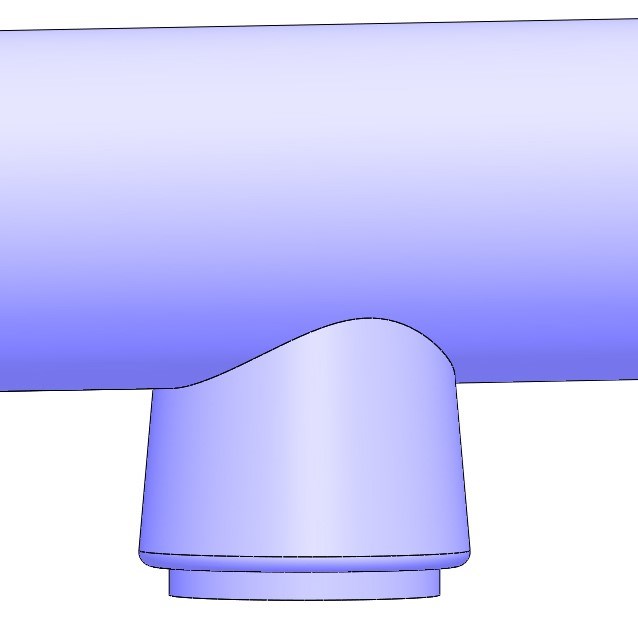
FIG 10 A well-designed runner puller.
• Shortened ejector pins with a conical tip are used to stabilize a runner from shifting or rolling over during ejection, as shown in Fig. 11.
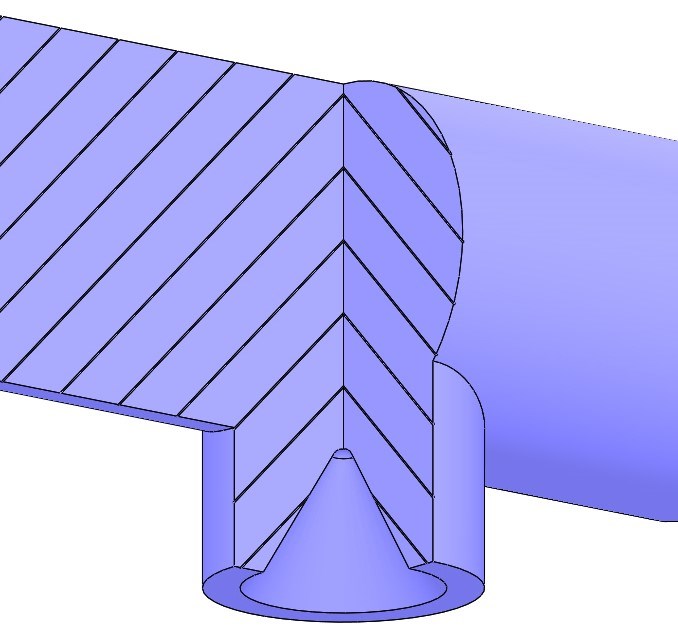
FIG 11 Cross-section of a runner stabilizer.
• Ideally, an ejector pin should be located at each runner intersection, because as the massive runner shrinks, it will try to stick on the inside corners.
• If a full-round runner sticks on the cavity side of the mold, instead of using pullers, you can add undercuts on the ejection side. A teardrop-shaped undercut is best for preventing flakes or shavings, as shown in Fig. 12.
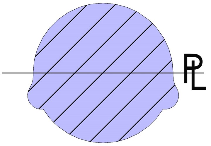
FIG 12 A teardrop-shaped runner undercut.
• Consider the location of any runner undercuts. They should be at or near an ejector pin to prevent the runner from bending or cracking during ejection.
• An inexpensive way to delay the ejection of a runner (or a part), without having to incorporate a two-stage ejection system is shown in Fig. 13. The pins are well supported and have positive return. This design can help reduce flaking from sub-gated parts.
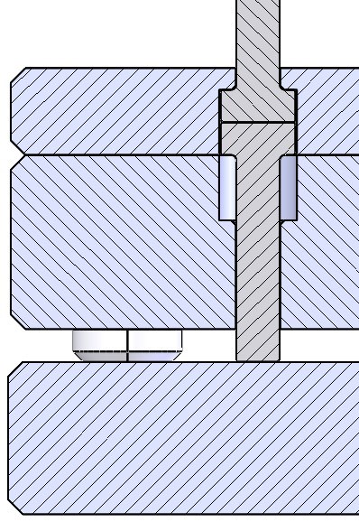
FIG 13 A delayed ejector design.
Venting
• Specify the vent locations, depths and widths on the mold drawing. Do not leave venting up to the toolmaker’s discretion.
• Some moldmakers and molders do not like to add vents until after the first sampling. This can lead to an erroneous fill pattern. At the very least, add vents at the last place to fill.
• Try to add a runner vent as close to the gate as possible.
Note: Special thanks to Roy Glenn, a retired moldmaker and mold designer, for his valued input on this month’s column.
About the Author: Jim Fattori is a third-generation molder with more than 40 years of experience in engineering and project management for custom and captive molders. He is the founder of Injection Mold Consulting LLC in Pennsylvania. Contact: jim@injectionmoldconsulting.com;
injectionmoldconsulting.com


Related Content

A Simpler Way to Calculate Shot Size vs. Barrel Capacity
Let’s take another look at this seemingly dull but oh-so-crucial topic.
Read More
Why (and What) You Need to Dry
Other than polyolefins, almost every other polymer exhibits some level of polarity and therefore can absorb a certain amount of moisture from the atmosphere. Here’s a look at some of these materials, and what needs to be done to dry them.
Read More
Density & Molecular Weight in Polyethylene
This so-called 'commodity' material is actually quite complex, making selecting the right type a challenge.
Read More
How to Set Barrel Zone Temps in Injection Molding
Start by picking a target melt temperature, and double-check data sheets for the resin supplier’s recommendations. Now for the rest...
Read MoreRead Next

Tooling: How to Properly Size, Gates, Runners and Sprues, Part 3
Get the sprue, runner and gate sizes close to ideal the first time around.
Read More
Tooling: How to Properly Size, Gates, Runners and Sprues, Part 2
Get the sprue, runner and gate sizes close to ideal the first time around.
Read More
Tooling: How to Properly Size Gates, Runners and Sprues, Part 4
How to get the sprue, runner and gate sizes close to ideal the first time around.
Read More