
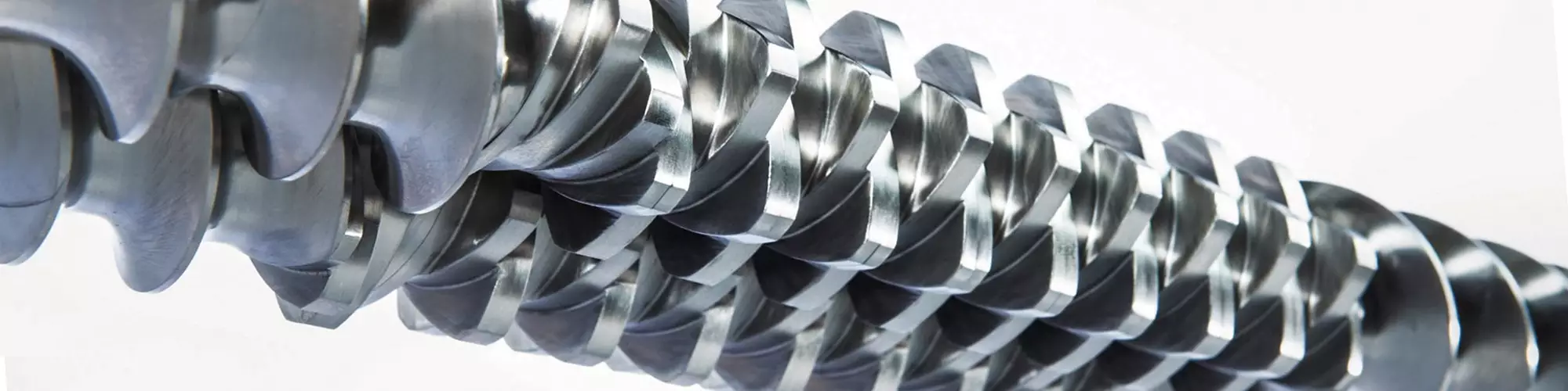


The corotating, intermeshing twin-screw extruder (TSE) is the compounding industry’s most prevalent device for continuous mixing of polymers with additives and fillers (Fig. 1) . Exotic formulations that utilize atypical active ingredients are also processed on this type of machine. Materials exposed to high shear and temperatures will degrade. Almost every product benefits by strategically managing how shear (and energy) is imparted to the materials being processed and is measured by the resulting melt temperature.
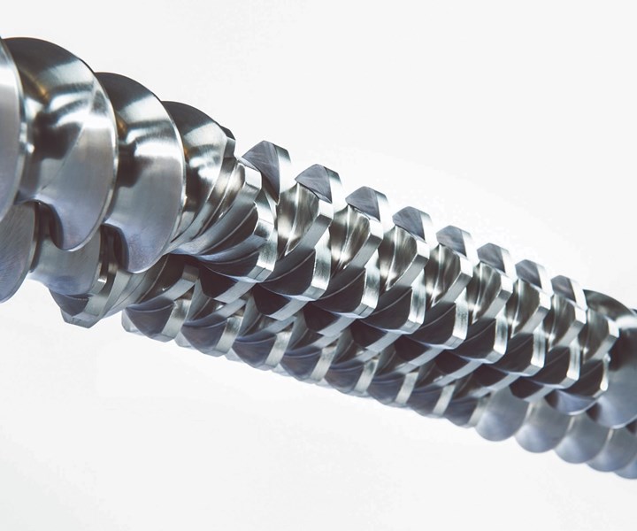
FIG 1 Twin-screws are powerful energy-input devices, with energy primarily derived from the motor.
Various factors must be considered to manage and control the melt temperature. In this article, emphasis will be given to OD/ID ratio, the melting zone in the screws, and front-end design.


Twin-Screw Extruder Theory & Design Basics
TSEs utilize segmented screws that are assembled on high-torque splined shafts (Fig. 2). . Barrels are also modular and utilize liquid cooling. The motor inputs energy into the process via rotating screws. Feeders meter materials into the TSE process section, and the screws’ rpm is independent and set to optimize processing efficiencies. Segmented screws and barrels, in combination with the controlled pumping and wiping characteristics of the corotating screws, allow screw/barrel geometries to be matched to the process tasks. Solids conveying and melting occurs in the first part of the process section. Next come screw elements for mixing and devolatilization. Discharge elements then build and stabilize pressure to a die or front-end device.
Almost every product benefits by strategically managing how shear (and energy) is imparted into the materials being processed and is measured by the resulting melt temperature.
The free volume in the process section is related to the OD/ID ratio, which is defined by dividing the outside diameter (OD) by the inside diameter (ID) of each screw. Deeper screw flights result in more free volume and a lower average shear rate, but with less torque, since there will be a smaller screw-shaft diameter.
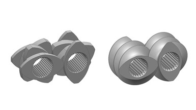
FIG 2 Corotating twin-screw elements with asymmetrical spline shaft design.
Asymmetrical splined shaft designs offer optimum power-transmission efficiency so that a smaller shaft diameter can transmit higher torque than otherwise. This is accomplished by isolating the tangential force vector transmitted from the shafts to the screws by the motor. The combination of higher torque, lower average shear, and larger OD/ID ratio has proven beneficial for many processes.
In Leistritz nomenclature, the HP series has a 1.55/1 OD/ID ratio and uses a symmetrical splined shaft design, and the MAXX series uses a 1.66/1 OD/ID ratio with an asymmetrical splined shaft. Increasing the OD/ID ratio increases the free volume by approximately 20%, along with a higher torque rating.
What Experiments Revealed
Experimental data was generated comparing 1.5/1 OD/ID and 1.66/1 model TSEs (Fig. 3). Process sections were interchangeable and mated to the same gearbox. Initial tests were performed with a neat resin with a 40:1 L/D process section and 40-hp motor.
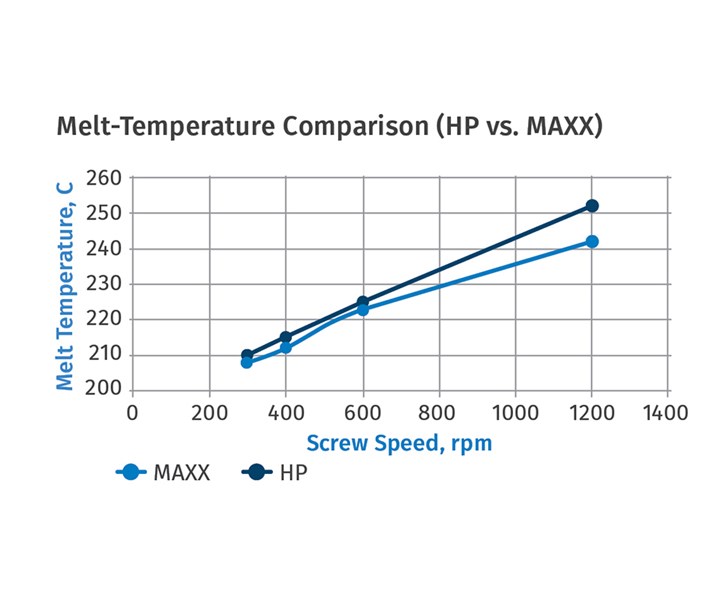
FIG 3 Results of tests where LDPE powder feedstock with 12 MFI was processed on a ZSE-27 HP (27 mm diam. screws, 1.5/1 OD/ID ratio) and a ZSE-27 MAXX (28.3 mm, 1.66/1 OD/ID). In each instance, the rate-limiting factor was the volumetric feed capacity. Melt temperatures were lower for the 1.66/1 OD/ID ratio (even at higher throughput rates) due to a lower specific-energy input (kWh) into each kg being processed and the gentler mixing effect associated with deep-flighted 1.66/1 OD/ID screw geometry.
LDPE powder feedstock with a 12 MFI was processed on a ZSE-27 HP (27 mm diam screws, 1.5/1 OD/ID ratio) and a ZSE-27 MAXX (28.3 mm screws, 1.66/1 OD/ID). In each instance, the rate-limiting factor was the volumetric feed capacity. The 1.66/1 OD/ID ratio made it possible to feed more material to the feed throat before encountering feed limitation. The increase in achievable feed rate was approximately 20% and comparable to the increased free volume associated with the higher OD/ID ratio. At elevated screw rpm (greater than 800), the percentage increase was not as pronounced, as the higher screw-tip velocity seemingly had a “propeller” effect that somewhat inhibited feeding.
The combination of both higher torque, lower average shear, and larger OD/ID ratio has proven beneficial for many processes.
The corresponding melt temperatures were lower for the 1.66/1 OD/ID ratio (even at the higher throughput rates) due to a lower specific-energy input (kWh) into each kg being processed and the gentler mixing effect associated with deep-flighted 1.66/1 OD/ID screw geometry.
A series of additional experiments were performed on the ZSE-27 MAXX (1.66 OD/ID) to compare the resulting melt temperature for different melting-zone screw configurations (Fig. 4) with a 2 MFI PP pellet resin. An “aggressive” melting zone with melting completed by barrel position 3 (12 L/D) was compared with an “extended” melting zone, where melting was completed by barrel position 4 (16 L/D). A single kneading-block set was used after melting in an attempt to isolate and compare the different melting-zone configurations and the resulting melt temperature. A low-pressure discharge die was used to minimize the effects of pressure on melt temperature. Both flush and immersion melt-temperature probes were utilized in the experiments. Tests were performed with various rates and screw rpm.
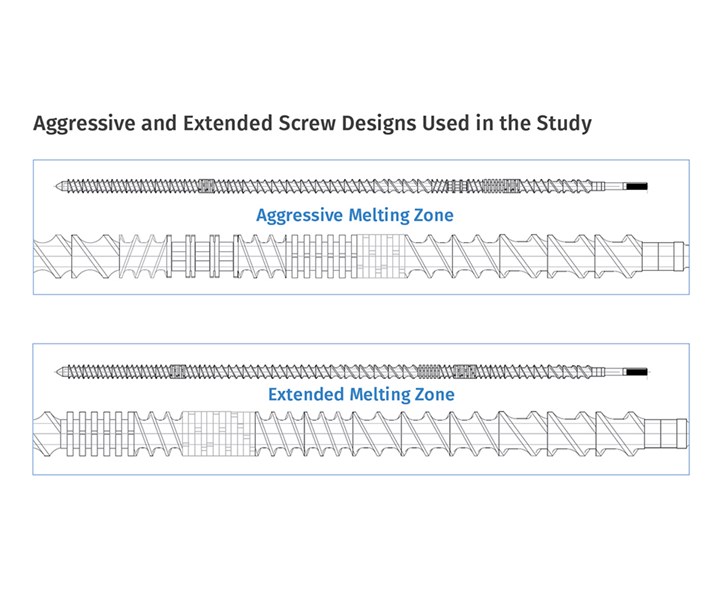
FIG 4 Experimental data was collected on a ZSE 27 MAXX twin-screw extruder. (28.3 mm screws, 1.66/1 OD/ID ratio). A 2 MFI PE pellet resin was processed, the temperature profile was optimized, and various screw speeds were tested. In each instance, the melt temperature with the aggressive design was much higher than with the extended melt-zone design.
The aggressive melting-zone design utilizes neutral/wide disk kneading-block elements and a reverse element to achieve full melting of the polymer by barrel zone 3. The goal of the aggressive melt zone might be to specify a shorter L/D, or to free up space in latter parts of the process for additional unit operations, i.e. injection, mixing or devolatiliation.
In comparison, the extended screw design utilizes narrow disk kneading-block elements with less intensive shear-stress input into the polymer, which results in more gradual melting of the polymer. The goal of the extended melt zone is to reduce the melt temperature and shear-stress exposure for the materials being processed. After melting, a single kneading-block section was integrated into the screw design to minimize temperature rise inherent in mixing.
The temperature profile was optimized and various screw rpms were tested. The data in the accompanying melt-temperature graphs was obtained with a handheld immersion probe.
In each instance, the melt temperature with the aggressive design was much higher (10° to 30° C) than with the extended melting-zone design (Fig. 5). It is worth noting that the immersion probe measured significantly higher temperatures (sometimes 20° to more than 40° C) than the flush melt probe. It is evident that when a melt probe is not fully immersed into the polymer melt, the melt-temperature reading is influenced by the metal adapter setpoint—lower than actual, and not accurate.
Higher temperatures inherent with the aggressive screw design resulted in significant degradation, as indicated by smoke and discoloration at elevated screw rpm.
The attainable rates were also maximized for both designs by targeting 85% operating torque and increasing the rate until that threshold occurred. The extended melting-zone design resulted in both higher throughput rates than the aggressive screw design and lower melt temperatures. Comparing the two melting zones (aggressive and extended) showed that the aggressive melting zone caused a significant temperature rise and lower attainable throughput rates than with the extended melting zone. Higher temperatures inherent with the aggressive screw design also resulted in significant degradation, as indicated by smoke and discoloration at elevated screw rpm.
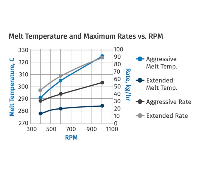
FIG 5 Rates were maximized for both designs by targeting 85% operating torque and increasing the rate until that threshold occurred. The extended melting-zone design resulted in both higher rates than the aggressive screw design and lower melt temperatures. Comparing the two melting zones (aggressive and extended), the aggressive zone caused a significant temperature rise and lower attainable rates than with the extended melting zone. The higher temperatures inherent with the aggressive screw design also resulted in significant degradation, as indicated by smoke and discoloration at elevated screw rpm.
Other Factors That Impact Melt Temperature
The screw design in the melting zone directly impacts the melt temperature, and is significant. Temperature setpoints in this zone will also contribute to the the melt temperature. Perhaps counter-intuitively, higher setpoints generally result in a lower melt temperature. Accordingly, in this study a reverse temperature profile (higher temperature setting in the first part of the process) was selected to lessen the melt-temperature rise associated with the melting zone. An optimized melt zone is a good start.
In addition to melting, it is apparent that the screw must also be designed to melt and mix without excessive shear inducement. The use of wide kneading blocks and reverse elements for mixing will result in more energy being imparted to the process and further raise the melt temperature, and must be considered when designing the screw.
Often overlooked, pressure generation at the discharge of the TSE also adds to the melt temperature. The more restrictive the front end, the higher the pressure and corresponding melt temperature. The temperature rise associated with the front-end design can be estimated as follows:
∆ T (C) = ∆ P (bar) ÷ 2
∆ T = Change in temperature (C)
∆ P = Change in pressure (1 bar = 14.503 psi)
For example, if a TSE is processing 500 kg/hr and the die pressure is 40 bar (580 psi), then the associated melt-temperature rise can be 20° C (∆T = 40÷2).
This formula is meant to be insightful, if not necessarily accurate, as screw rpm, the geometry of the discharge screw elements, temperature setpoints, and formulation viscosity are all factors in the resulting melt temperature. The point is that the front-end design must be considered when managing melt temperature in a corotating twin-screw extruder.
With corotating TSEs, screw design, front-end configuration, temperature settings and operating conditions all impact what the formulation “experiences” in the TSE process section and directly influences the properties of the final part. Managing melt temperature and minimizing degradation is key to making high-quality parts and must be managed to achieve optimization of any polymer process.
ABOUT THE AUTHORS Charlie Martin is president and general manager of Leistritz, Somerville, N.J., a leading supplier of twin-screw extrusion equipment for compounding, devolatilization, direct extrusion, pharmaceutical, and other applications. Martin has been in the extrusion industry for more than 30 years, is a member and former chair of the SPE Extrusion Div., and has given dozens of papers at various technical conferences on a range of extrusion topics around the world. Contact: (908) 685-2333; cmartin@leistritz-extrusion.com; extruders.leistritz.com.
Brian Haight is the assistant lab manager at Leistritz, with responsibilities that include operation of extruders, process support, and training. He is a graduate of New Jersey Institute of Technology with a Bachelor’s degree in Chemical Engineering and a Master’s degree in Pharmaceutical Engineering. Contact: bhaight@leistritz-extrusion.com.


Related Content

How to Maintain Pelletizing Quality When Acid Attacks
Developments in the chemistry of polymers and additives have made corrosion a real problem in pelletizers. Here’s how to ward it off.
Read More
LFT-D Thrives in Automotive and Other Durables
Teijin Automotive acquires its 10th direct long-fiber thermoplastic system as demand for this technology soars.
Read More
The Path to Pellet Perfection
In underwater pelletizing, numerous variables in the equipment, process and material affect pellet shape, consistency and quality factors such as fines. Defining the “perfect” pellet depends on the conditions of end use, and achieving that ideal requires understanding of the causes of imperfections.
Read More
Configuring the Twin Screw Extruder: Part 4
For many compounding operations, material is fed to the extruder at the feed throat. This is the case when feeding a single polymer or a blend of polymers mixed with solid additives. Some ingredients, however, present a challenge in feeding. Here’s how to solve to them.
Read MoreRead Next

‘Follow the Plan’ When Installing and Commissioning Compounding Lines
A fully operational and documented system doesn’t happen by chance. An efficient, well-designed installation plan, prepared well in advance, will put you on the path to maintaining a timeline and budget.
Read More
Strand Pelletizing: Follow These Steps to Determine Your Water Bath Length
Use heat-transfer equations as a shortcut to get you in the ballpark of how long your pelletizing water bath should be.
Read More
Follow These Guidelines to Select the Right Pelletizing System
Which pelletizing system is right for your application? Is the one you’re using today necessarily the right choice for tomorrow? Here’s is an analysis that can help you decide among the three major options.
Read More