
Hitting the Numbers, Part 1: Communication is Key
Start with an up-front review, discussion and collaboration with the customer.

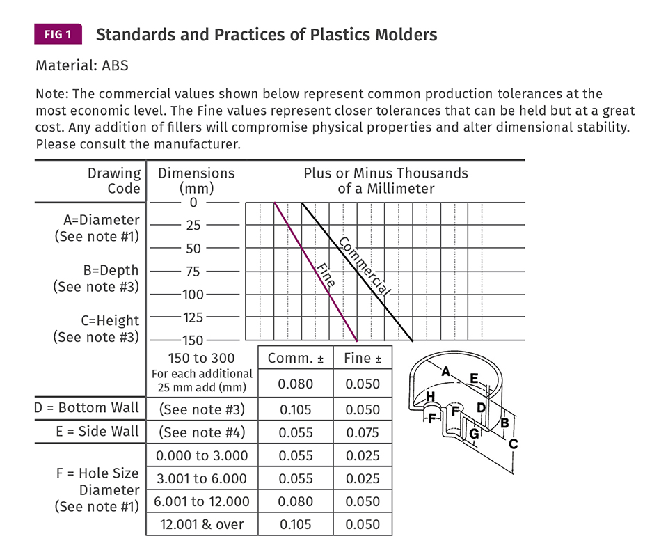
Source: The Plastics Industry Association’s publication, Standards & Practices of Plastics Molders.


This is part one of a two-part series about the best practices for Hitting Critical Numbers. Read this article for more information on this subject.
The biggest tooling problem I know of has little to do with cutting steel. The problem is failing to consider, obtain and verify all the pertinent information up front to ensure the mold will produce a dimensionally, functionally and aesthetically acceptable part.
The customer supplies a tool maker or molder with a 3D solid model and a 2D drawing and says, “Build me a mold to produce parts as per the supplied drawings.” Cutter paths are generated from the solid model, but parts are inspected to the 2D drawing. How do you know the 2D and 3D information is identical? Even though a good 3D CAD program can automatically update the 2D drawing, it can’t change the revision level and print itself out. Additionally, since dimensions on a 2D drawing can be manually overridden, the final or “Released for Production” 2D drawing should be checked to ensure it matches the 3D model.


Two-dimensional drawings can have anywhere from 3 to 300 dimensions on them. Part designers often leave out the critical tolerances or neglect to adjust the precision of each dimension to what is actually required. The industry standard is linear dimensions are specified to three decimal places, radii to two places, and angles to one place. But on occasion, you will see a complex threaded closure with dimensions drawn to two-place precision, or a simple pet toy drawn to four-place precision. It’s what makes our jobs interesting.
The title block in the corner of the part drawing specifies the generic tolerances based on the precision of a dimension—typically ±0.005" for three-place dimensions. While ±0.005 is not a problem for the tool maker, it can be a real challenge for the molder. And if the molder can’t hit the numbers, fingers usually get pointed back at the tool maker.
Unless you’re molding something as small and precise as a detonator cap for an airbag, the majority of the dimensions on a drawing usually don’t need to be held to within 0.005". The customer should identify the truly critical dimensions that affect the form, fit, and function of the part. The critical dimensions should then be evaluated to see if specific areas of the mold can be made “steel safe” by leaving on extra steel or by installing an insert, in case adjustments need to be made after the initial sampling to bring the part into spec. These additional machining and re-sampling costs should be included, if not noted as a separate line item, on the mold quotation.
Almost all thermoplastic materials shrink when they transform from a liquid state to a solid state. Let’s say you are molding a part 0.125" × 0.5" × 5" and the material shrinkage percentage is 0.50% (or a shrinkage ratio of 0.005 in./ in). The thickness of the part will theoretically shrink 0.0006", the width 0.0025", and the length 0.0250". Obviously, the larger the dimension, the greater the total amount of shrinkage. Toolmakers and molders know this all too well. Many customers and part designers don’t—especially if their background is in metal fabrication. A drawing may have a large part dimension, such as 15" with a title-block tolerance of 0.005". That’s probably not going to happen. This needs to be explained to the customer.
The Plastics Industry Association (formerly known as the Society of the Plastics Industry) has an excellent publication entitled Standards & Practices of Plastics Molders. The section on Molding Guidelines lists “commercial” and “fine” tolerances based on material type and part size (see Fig. 1).
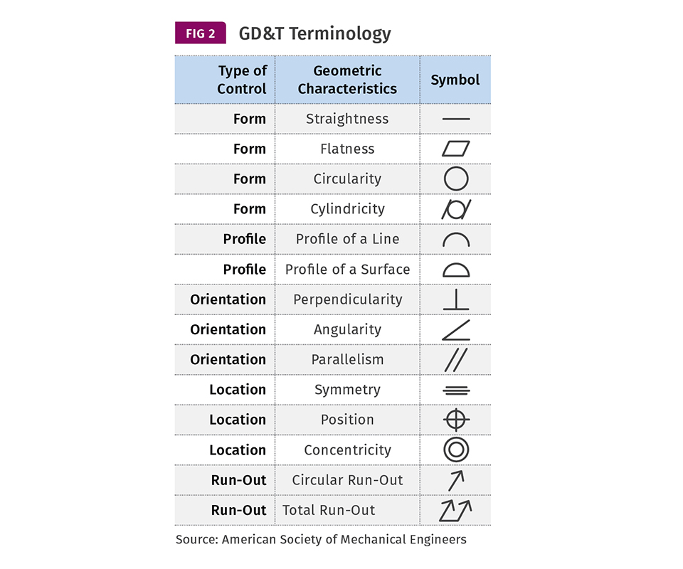
The American Society of Mechanical Engineers’ Y14.5-2009 standard is considered the authoritative guideline for geometric dimensioning and tolerancing (GD&T). Unfortunately, many part designers don’t use GD&T nomenclature on their drawings (see Fig. 2). But that doesn’t mean characteristics such as straightness, flatness, concentricity and position aren’t important to them.
Drawing notes such as “Part to be free of flash and sharp edges” or “Trim gates flush” need to be taken seriously because they may require a secondary operation. The only thing worse than stringent notes like these are no notes at all. Aesthetic parameters are rarely defined on a drawing and yet are always important. A customer once told me, “I don’t care about weld lines, sink, flash or gloss. They don’t affect the function of the part. But I have to put it on a purchasing agent’s desk and convince him my parts are better.”
Don’t dismiss cryptic notes such as, “Must conform to XYZ Company specification # SP-4265 and mate with P/N 3127.” If the customer neglects to provide the relevant information, mating parts, etc., that may not exonerate you if the parts don’t function properly.
Check to see if the draft angles are specified in the correct direction and are sufficient to release the part from both the cavity and the core, especially if the mold is textured. (Has the surface finish even been specified?) If the draft is insufficient, the customer must be informed and the part design modified. What does this have to do with hitting the numbers? If the tool maker uses up some or all of the dimensional tolerances to account for the necessary draft in the mold, the molder is forced to hit the numbers perfectly with no margin for error.
The customer will usually specify the material type, such as ABS or nylon. Even if it specifies a particular manufacturer and grade of material, ask if alternate materials of the same type are permissible. Different grades of materials have different specific gravities, molecular weights, molecular-weight distributions, and other physical properties, which can impart slightly different shrinkage factors and processing attributes. The same is true for the colorant. Changing the brand or grade of material or colorant could give you the extra edge needed to get the part into spec. As a precaution, ask the customer if the parts will ever be made in more than one type of material, or in more than one color. If so, the second set of cavities and cores, or a different hot- or cold-runner system may be required to hit those numbers.
To avoid any potential disagreements in the future, have the parts inspected by an impartial third party. They have the equipment and experience to measure plastic parts accurately. Their cost and lead time are often better than what you can achieve in-house. Also request that the 2D drawing is revised after the final sampling, so as to change any “out-of-spec” non-critical dimensions to the new nominal value.
It’s incumbent on both the tool maker and the molder to know exactly what the customer’s requirements and expectations are and how the part is going to be used before quoting a job. A drawing that looks like a “no brainer” could end up being a “no-quote” after all the pertinent questions are asked and answered.
About the Author
Jim Fattori
Jim Fattori is a third-generation injection molder with more than 40 years of molding experience. He is the founder of Injection Mold Consulting LLC and is also a project engineer for a large, multi-plant molder in New Jersey. Contact: jim@injectionmoldconsulting.com.


Related Content

How to Start a Hot-Runner Mold That Has No Tip Insulators
Here's a method to assist with efficient dark-to-light color changes on hot-runner systems that are hot-tipped.
Read More
How to Select the Right Tool Steel for Mold Cavities
With cavity steel or alloy selection there are many variables that can dictate the best option.
Read More
Where and How to Vent Injection Molds: Part 3
Questioning several “rules of thumb” about venting injection molds.
Read More
How to Mount an Injection Mold
Five industry pros with more than 200 years of combined molding experience provide step-by-step best practices on mounting a mold in a horizontal injection molding machine.
Read MoreRead Next

Troubleshooting Screw and Barrel Wear in Extrusion
Extruder screws and barrels will wear over time. If you are seeing a reduction in specific rate and higher discharge temperatures, wear is the likely culprit.
Read More
Processor Turns to AI to Help Keep Machines Humming
At captive processor McConkey, a new generation of artificial intelligence models, highlighted by ChatGPT, is helping it wade through the shortage of skilled labor and keep its production lines churning out good parts.
Read More
People 4.0 – How to Get Buy-In from Your Staff for Industry 4.0 Systems
Implementing a production monitoring system as the foundation of a ‘smart factory’ is about integrating people with new technology as much as it is about integrating machines and computers. Here are tips from a company that has gone through the process.
Read More