
How ‘Hydro Wedges’ Reduce Screw Wear
Using them only in the melting section provides for greater design freedom and negates the impact these devices can have on output and melt temperature.
.jpg;width=70;height=70;mode=crop;format=webp)
Hydrodynamic bearings are used to maintain shaft centering and reduce screw-flight.
A "hydro wedge" has to be on the pushing side of the flight to have any effect, but testing confirmed there is pressure development due to the moving surfaces. In general, the effect is useful from a flight helix angle of 10-20°, and a wedge angle of 3-5° off the flight or mixer centerline seems to develop the most pressure.
The hydro wedge can be relegated to only the sections of the screw showing rapid wear, typically the melting section and Maddock mixer, where there is more discretion in the design and the dimensions can be more easily manipulated to compensate for the slight reductions in output and elevation in melt temperature. Here, on the Maddock mixer, a series of wedges is applied to both the bands at both ends and to the sealing flights.


Several variations of flight wedges, such as chamfers, radii, and the like, are offered as devices to reduce screw wear. Screw flights wear when they make contact the barrel wall because the lubricating film of polymer in the flight clearance is missing. Without the lubricating film, the flights are in metal-to-metal contact with the barrel.
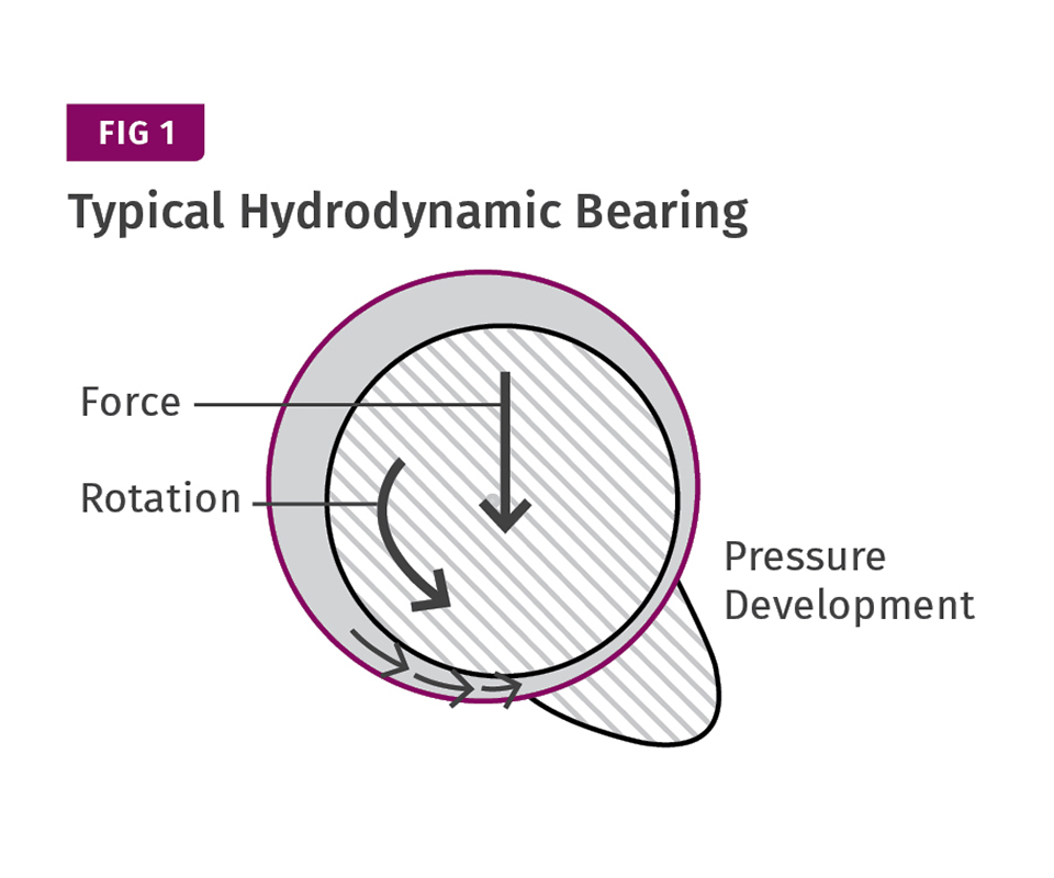
The screw is centered in the barrel at the drive end by the reducer—assuming proper alignment of the feed throat and barrel—but is free to move at the other end. The polymer-filled channels tend to hydraulically support the screw when rotating. The screw isn’t just bouncing around, but still continuously contacts the barrel wall end. The polymer-filled channels tend to due to moving radial pressures developed in the screw. The screw flights provide the main centering and will not wear as long as a lubricating polymer film is maintained between flight and barrel wall. When that film is squeezed out, the flights will gall, causing wear, even with the most advanced materials of construction. A concept widely used to maintain shaft centering and reduce wear is a hydrodynamic bearing, as shown in Fig. 1.
Any eccentricity of the shaft “drags” the lubricant into the gap between the shaft and bearing and creates an increase in film pressure. The magnitude of the pressure development increases with the relative velocity, film viscosity and decreasing film thickness. The pressure development is maximum near the point of minimum film thickness. The whole effect is to re-center the shaft in the bearing. The greater the eccentricity, the greater the pressure development, making it somewhat self-correcting as the force increases. Hydrodynamic bearings have been used in a number of twin-screw applications to support kneading sections, and in melt pumps to support the gears; and there are also a number of fully round mixing sections in which they are used to reduce wear.
Generally, it is difficult to use a hydrodynamic bearing in single screws without restricting the output. The concept was thoroughly investigated in the early 1980s by Union Carbide when the first LLDPE polymers were introduced. The prevalent screw designs at that time for polyolefins were conventional screws with Maddock-style mixers. The reduced shear sensitivity of LLDPE compared with LDPE caused very high, unbalanced pressures to develop in these screws—particularly in the melting or compression section—and in the Maddock mixers, resulting in high wear.
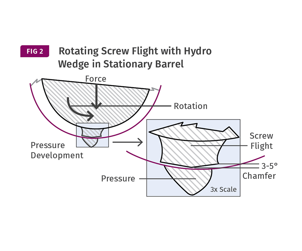
To get a hydrodynamic effect depends on forming a converging wedge between the surfaces moving at different velocities. That is very difficult to achieve with a narrow flight, since any pressure created acts in all directions and tends to squeeze the film out of any wedge before any significant pressure level is reached. The helix angle also negatively affects the pressure development in the flight clearance because the drag force is largely circumferential, pulling the polymer out of the wedge if it is on the trailing side.
The result of the studies done in the 1980s determined that any “hydro wedge” had to be on the pushing side of the flight to have significant effect, and it worked more like a scoop than the classic hydrodynamic support. However, testing confirmed there was pressure development due to the relative velocity between the surfaces—but it is a daunting task to mathematically quantify. In general, the effect was tested to be useful from a flight helix angle of 10-20°, and a wedge angle of 3-5° off the flight or mixer centerline seemed to develop the most pressure, as shown in Fig. 2.
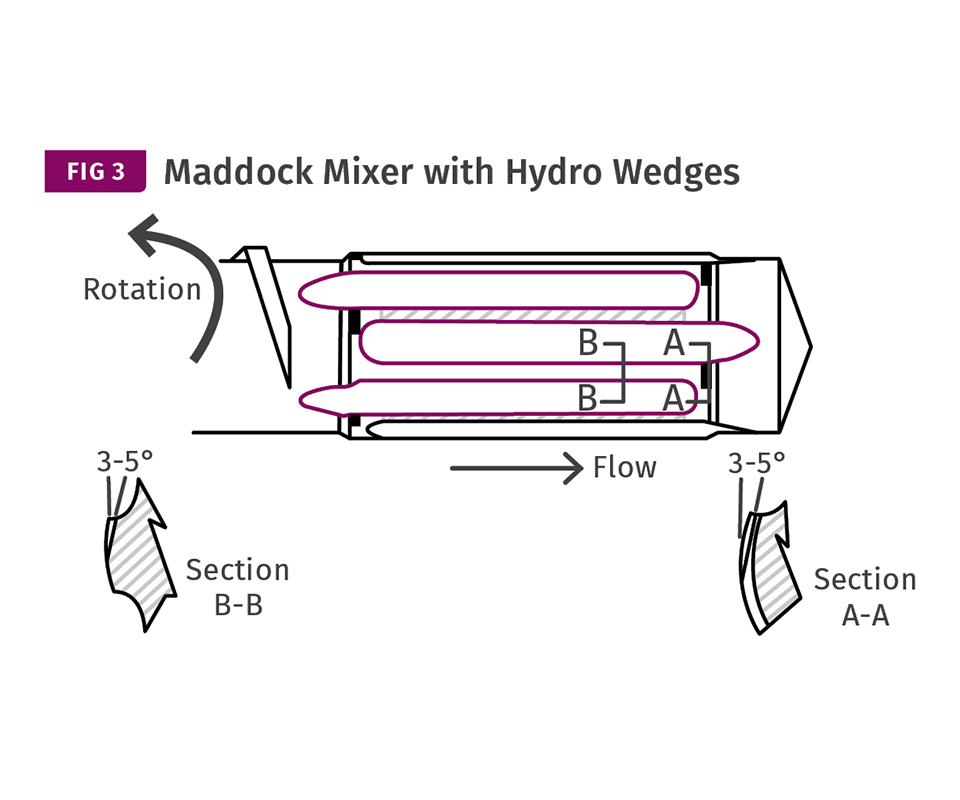
However, because of the leakage, a slightly wider than normal flight was found to be advantageous. That can have a minor negative effect on output and melt temperature, but the hydro wedge can be relegated to only the sections of the screw showing rapid wear, typically the melting section and the Maddock mixer. Fortunately, in these sections there is some discretion in the design, and the dimensions can be more easily manipulated to compensate for the slight reductions in output and elevation in melt temperature. For the Maddock mixer, a series of wedges was applied to both the bands at both ends and to the sealing flights, as shown in Fig. 3.
The addition of the wedges made no measurable change in performance of the screws, yet the wear resistance was greatly improved in both areas, which supported the theory of developing radial centering pressure.
The hydro wedge for screw flights and Maddock mixers was originally patented by Union Carbide but the patents expired many years ago. The designs were supplied to LLDPE processors to promote LLDPE usage until being largely replaced by barrier screws. Hydro wedges still offer benefits with any high-viscosity, crystalline polymer where wear causes a limitation in output by restricting the design. Shear-type, dispersive mixers can benefit in almost all cases if the proper wedge geometry can be obtained. Hydro wedges have also been used to reduce wear rates with filled polymers by maintaining a more uniform flight clearance and by “flushing” fillers through the flight clearance to provide improved lubrication.
ABOUT THE AUTHOR: Jim Frankland is a mechanical engineer who has been involved in all types of extrusion processing for more than 40 years. He is now president of Frankland Plastics Consulting, LLC. Contact jim.frankland@comcast.net or (724)651-9196.


Related Content

How to Estimate and Control Head Pressure
You rightfully worry about melt temperature, but don’t overlook head pressure, because the two are closely linked and will influence line performance.
Read More
The Importance of Viscosity in Melting
The calculations required to determine the right melt temperature for each polymer are complicated. Knowing the power-law coefficient and the consistency index of the polymer you run might prove useful.
Read More
Cooling the Feed Throat and Screw: How Much Water Do You Need?
It’s one of the biggest quandaries in extrusion, as there is little or nothing published to give operators some guidance. So let’s try to shed some light on this trial-and-error process.
Read More
Roll Cooling: Understand the Three Heat-Transfer Processes
Designing cooling rolls is complex, tedious and requires a lot of inputs. Getting it wrong may have a dramatic impact on productivity.
Read MoreRead Next

Extruding with Fillers
You can use the reference point from processing unfilled polymer to determine whether you can run filled resin on your current system.
Read More
Why (and What) You Need to Dry
Other than polyolefins, almost every other polymer exhibits some level of polarity and therefore can absorb a certain amount of moisture from the atmosphere. Here’s a look at some of these materials, and what needs to be done to dry them.
Read More
Understanding Melting in Single-Screw Extruders
You can better visualize the melting process by “flipping” the observation point so that the barrel appears to be turning clockwise around a stationary screw.
Read More