INJECTION MOLDING: The Importance of Nominal Wall For Lightweighting Molded Parts
Establishing a nominal wall is one of the most important decisions an engineer makes when designing parts. Understanding how design changes will impact the manufacturing process is critical to ensure the part performs as expected.
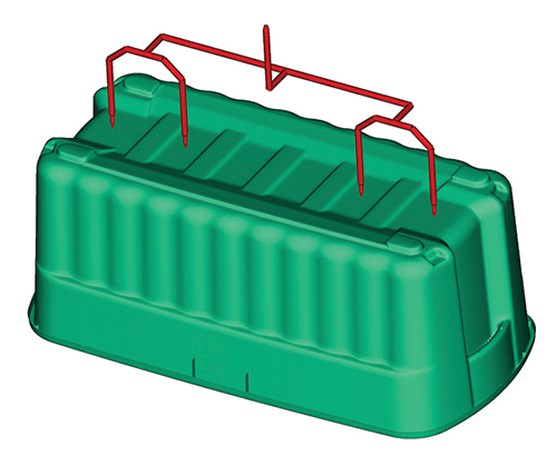
Manifold A used four drops to fill the part with all the drops located on the part centerline.
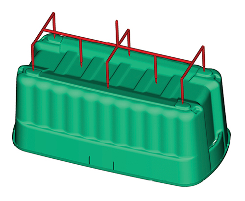
Manifold B increased the number of drops and moved them closer to the sidewalls of the container to decrease the flow length.
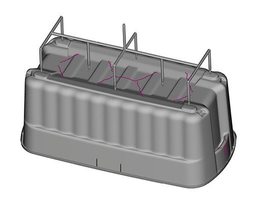
By increasing the number of drops with Manifold B, the number of weld lines increased on the bottom of the container.
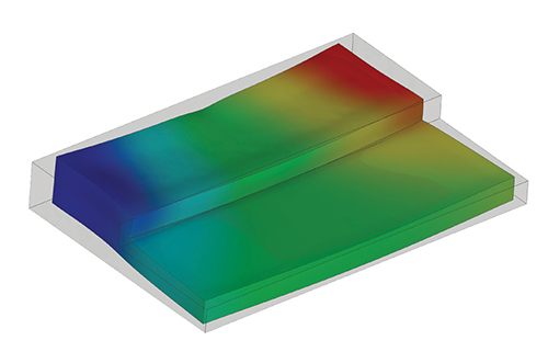
Varying the wall thickness of the plastic part leads to non-uniform shrinkage that can lead to excessive warpage.
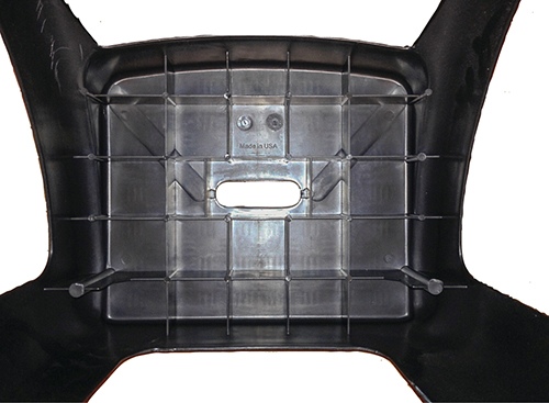
Image shows the incorporation of a flow leader (localized thickness increase) to assist molding a plastic part.


Most engineers who have dealt with plastics in their careers have heard that the first rule in design is that the part should maintain a uniform wall thickness. The principles of this rule are deeply rooted in manufacturing. But with the current trends to lightweighting products and reducing material consumption, designers are often making decisions regarding the nominal wall based solely on part performance.
Not considering the effects of the nominal wall on the manufacturing process early in the design phase can result in a narrow processing window or inability to manufacture the part to print. When these issues arise during initial molding trials, the burden is usually placed on the molder to make the product work. At this point, the choices for solving the issues are often limited, and the solution could lead to undesirable performance when the part is in service.


While manufacturing is important, the preliminary decision of establishing a nominal wall should be dictated by the functional performance requirements of the part. If the part doesn’t function no one will buy it. Considerations of acceptable stress levels and expected lifetime of the part should help designers in establishing the nominal wall. Previous experience and the correct interpretation of structural finite-element analysis (FEA) have made these decisions more reasonably attained during the preliminary design stages.
Once the minimum wall thickness has been established for performance, the designer’s thought should turn to manufacturing. The discussion here is limited to injection molding. Due to the inherent nature of the process, there are practical limits to how thin the walls can be made and still manufacture the part. Most conventional injection machines can generate 20,000 to 30,000 psi of plastic pressure to fill the mold. As a general rule of thumb, the pressure required to fill should be 50-75% of the capacity of the injection unit. This will allow for a stable molding process that can accommodate any natural variation that may arise in the molten plastic material.
If the wall thickness selected requires excessive pressure to fill the mold, then either the wall thickness needs to be increased, the flow length needs to be reduced, the material needs to be changed, or a combination of these three factors. A knee-jerk reaction to excessive pressures is to use an easier-flow material. Generally speaking, these easier-flow materials have a lower average molecular weight, which reduces the effective viscosity of the resin. While this can be done successfully, a holistic approach should be taken to see how the change in material will affect the short- and long-term performance of the product. This often requires more than just looking at a datasheet. An alternative approach to reducing the injection pressure while maintaining the desired nominal wall is either relocating the gate or adding additional gates to reduce the flow length.
HOW TO EVALUATE MOLDABILITY
Injection molding simulation can be used to determine the feasibility of manufacturing a part at a given wall thickness. Simulation allows the designer to account for the effects of all three factors (material viscosity, part thickness, and flow length) in the process and provides a prediction of the maximum injection pressure and clamp tonnage required to manufacture the part. This information helps determine how large a machine will be required.
If the predicted pressure or tonnage exceeds the capacity of the machine, an analyst can adjust one of the three parameters to evaluate how the process parameters would change and if it will increase the processing window of the part. By incorporating simulation into the design evaluation, these decisions can be made early in the design process and can help the designer judge whether the processing will affect part performance.
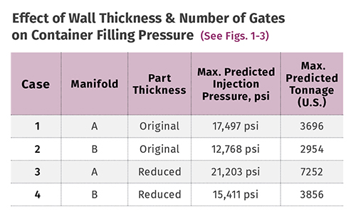
Figure 1 shows a container that was undergoing a design revision to minimize material consumption by reducing the wall thickness. The objective of the project was to be able to manufacture the container in the same size machine, but reduce the wall thickness by 10%. The container was to be filled with four drops located along the container centerline (Manifold A). A series of baseline simulations was performed to determine how the process was predicted to change as a result of the wall-thickness reduction. The analysis revealed that reducing the wall thickness by 10% would increase the predicted injection pressure by 21% and the predicted tonnage by 100% (see table). This resulted in both a pressure- and tonnage-limited process and would have required a larger press to mold the parts.
Therefore, it was determined that the wall-thickness reduction was not feasible with the current mold design. The customer did not want to change the material, and thus the manifold was modified and the number of drops was increased from four to eight (Manifold B), as shown in Fig. 2. Increasing the number of gates, and placing the gates farther away (closer to the sidewalls) reduced the flow length of the material in the cavity. The simulations revealed that the new manifold design would actually reduce the required injection pressure and only increase the predicted clamp force by 4%. This modified manifold design allowed the wall reduction to be achieved without the requirement of moving to a larger press. The simulation also allowed the designer to identify the location and number of weld lines to determine how they would influence the performance of the part, as shown in Fig. 3.
WHY MAINTAIN UNIFORM WALL THICKESS ?
Once the nominal wall thickness is established, it is important that the wall thickness remain as consistent as possible. Maintaining a uniform thickness will allow for the most uniform flow of the plastic through the part and allow the best possible processing. Since injection molding is a pressure-driven process, the molten polymer will take the path of least resistance. That means when there is a variation in wall thickness the plastic will preferentially flow through the thicker wall. Such preferential flow can lead to unbalanced filling patterns, air trapping, or formation of weld lines.
Additionally, plastics are inherently poor heat conductors, so by maintaining a uniform wall thickness the part will cool as uniformly as possible. This also means that, if packed properly, the part should shrink as uniformly as possible, and minimize residual stresses in the molded part. The equation below shows that the cooling time of a plastic part is directly proportional to the square of the wall thickness:
tcooling ∞ thickness2part
density
Therefore, if a 2-mm wall will take 1.76 sec to cool, then a 4-mm wall will take approximately 7 sec to cool. If these two wall sections are placed adjacent to one another, the 4-mm wall will want to shrink significantly more than the 2-mm wall, as shown in Fig. 4. As a result of this differential shrinkage, a stress develops that the part will want to relieve upon ejection, and the part can then exhibit excessive warpage. If the part design requires certain areas to act stiffer than others, there are better options than simply thickening up the wall. The addition of ribs, or profiling the part wall to achieve a stiffer part while maintaining the uniform wall thickness, will allow for more success than selectively increasing the part wall thickness. However, the dimensions of those features are still dictated by the wall with which they intersect.
SO I CAN'T VARY MY WALL THICKNESS?
Current applications for parts often make it difficult to maintain a constant nominal wall. Also, the conflicting requirements of part function and manufacturing do not always align to allow for the optimum mold construction. Here, a localized variation in wall thickness may be required to achieve the desired fill pattern or part performance. The requirement may be a result of an unbalanced fill pattern, non-ideal weld-line location, air trapping, or excessive warpage.
Whatever the reason, establishing a nominal wall will still help guide a designer on how much the part thickness can be altered. When a variation in wall thickness is required, these guidelines should be followed:
• Make any thickness transition gradual. As was shown in the previous section, abrupt thickness transitions can lead to variations in shrinkage and high residual stress in the molded part. This can lead to excessive part warpage or reduced strength.
• Minimize the variation in wall thickness to 25% in amorphous resins and less than 15% for semi-crystalline resins. The lower shrinkage rates of the amorphous resins allow for greater variation.
• Place the gate in the thickest region of the part. Locating the gate in the thickest wall section will allow for the thicker areas to be packed out better and will allow for more control over the packing stage, which can help minimize the formation of voids or sinks.
Establishing a nominal wall is one of the most important decisions an engineer makes when designing an injection molded plastic part. The nominal wall influences the overall dimensions of the part, the part performance, and the manufacturing requirements. Designers need to take a holistic approach on how to reduce the wall thickness of the part before making decisions.
Understanding how the design changes will impact the manufacturing process is critical to ensure the part performs as expected.
Related Content

How to Select the Right Tool Steel for Mold Cavities
With cavity steel or alloy selection there are many variables that can dictate the best option.
Read More
Understanding the ‘Science’ of Color
And as with all sciences, there are fundamentals that must be considered to do color right. Here’s a helpful start.
Read More
A Simpler Way to Calculate Shot Size vs. Barrel Capacity
Let’s take another look at this seemingly dull but oh-so-crucial topic.
Read MoreRead Next

Troubleshooting Screw and Barrel Wear in Extrusion
Extruder screws and barrels will wear over time. If you are seeing a reduction in specific rate and higher discharge temperatures, wear is the likely culprit.
Read More
Understanding Melting in Single-Screw Extruders
You can better visualize the melting process by “flipping” the observation point so that the barrel appears to be turning clockwise around a stationary screw.
Read More
Advanced Recycling: Beyond Pyrolysis
Consumer-product brand owners increasingly see advanced chemical recycling as a necessary complement to mechanical recycling if they are to meet ambitious goals for a circular economy in the next decade. Dozens of technology providers are developing new technologies to overcome the limitations of existing pyrolysis methods and to commercialize various alternative approaches to chemical recycling of plastics.
Read More