PART 2: The Importance of Consistent Fill Time
To make identical parts, you need to keep fill time constant. In part one we covered the why. Here’s the how.
.jpg;width=70;height=70;mode=crop;format=webp)
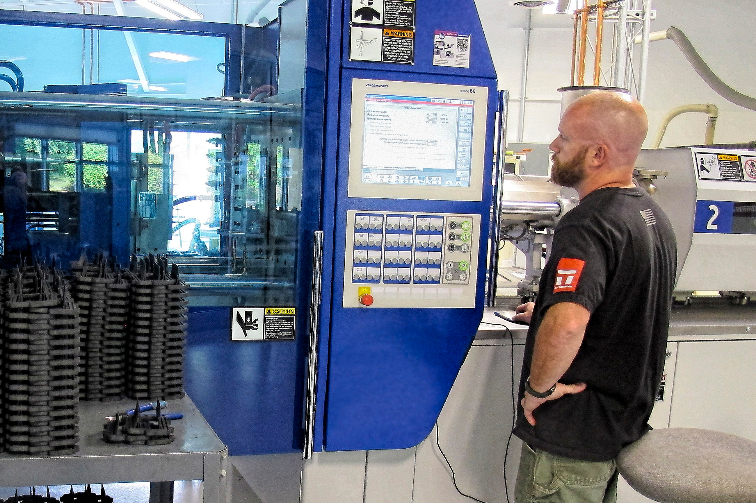
Perform a series of short shots to determine the appropriate Delta P for a particular injection machine. Setting that Delta P is the secret to consistent fill time.


Last month, in the first part of this two-part installment we focused on the reasons viscosity can change during injection molding. Because viscosity is a variable, keeping fill time constant minimizes the influence of these variations and provides a more stable process, and therefore more consistent parts. If driven to the same shear rate, viscosity variations can be minimized to provide a more consistent process. Run to run, shot to shot, summer to winter, and machine to machine—keep fill time the same and your process will be more consistent.
Once you find a fill time that makes good parts, it is the fill time for the life of the mold. So how do you maintain that fill time? There are differences of opinion in the industry. Some processors feel it is their job to adjust for viscosity changes. However, is it really possible, plausible—or the right strategy—to expect an operator to stand at the machine adjusting for viscosity variations? I prefer the strategy where the machine automatically adjusts for changes in viscosity, something like a car on cruise control. If you set up a machine correctly, it will provide consistent fill time. For most processes and machines, I target less than ±0.04 sec of variation. This does not apply if you have a fill time of 0.06 sec or a long fill time, so use common sense in establishing this range. Dare I say it: Do a DOE!


Any machine—open- or closed-loop, electric or hydraulic—will keep fill time constant, provided that it is set up with an appropriate Delta P. Delta P is the difference between the set first-stage pressure available and the peak pressure during injection or first stage. This, in combination with the required “load-compensation” circuit, will attenuate viscosity changes.
To find the appropriate Delta P for each machine (yes, they do vary), you need to find how much higher the set or available pressure for first stage is than the actual peak pressure during injection. The principle is the same for electric or hydraulic machines. The set or available pressure must be set higher than the peak (not transfer) pressure during injection. Peak pressure can be the same as the pressure at transfer but sometimes it is not, especially if you profile injection. For this procedure you must be able to read peak pressure during fill or first stage. The question is how much higher the allowable or set pressure should be than the peak pressure to allow the machine to control fill time.
THE DELTA P PROCEDURE
A caveat before we get into the nitty-gritty: Do not try this without proper at-the-press training. There are safety concerns for personnel and the possibility of damaging the mold or machine if one does not understand the procedure correctly. This procedure involves using high temperatures and pressures. If at any time, you are unsure of what will happen, stop and seek help.
- Bring the machine to steady-state operating conditions while molding parts and following all appropriate safety practices associated with the operation of the mold and machine selected. Ensure that you can read the peak hydraulic pressure during first stage or injection. This may not be the pressure at transfer, especially if you are profiling injection speeds. Location of the pressure-measuring device, gauge or transducer, should be after the flow-control valve or directly on the hydraulic injection cylinder (not near the pump). For electric machines, use the injection pressure displayed on the appropriate screen. Also, ensure you can measure the time from “injection-start” to when the screw reaches its cutoff (also known as transfer or switchover) position. This time is the fill time. This timer should count up and read to at least 0.01 sec. Ensure the machine is set to transfer from first to second stage via screw position.
- Ensure that the part will not stick if you make a short shot. Make sure the part is not filling during screw rotate. This can happen if the gate-seal time is long and the backpressure is high enough to push plastic into the mold during screw rotate. If a short shot sticks, use mold release or whatever is necessary to allow for easy part removal. Shorts will be made during the entire procedure. This is a maintenance task, not a process-development task.
- Take second stage (pack and hold pressure) off. That is, set second-stage pressure very low—for example, at 15 psi (1 bar) hydraulic or 100 psi (7 bar) plastic pressure. Do not set hold time to zero unless necessary. Taking second stage off by removing time on the timer may cause tool damage when you put time back on the second-stage or hold timer.
- Adjust the first-stage allowable timer for at least 3 sec longer than current fill time. This ensures there is always enough time on this timer for the screw to reach its cutoff position before this timer times out. For this step and the entire experiment, note: It is critical that all shots are short, and you are not bottoming the screw. Damage to the mold, machine and/or operator could result if you do not ensure making short shots with some cushion.
- Note peak pressure during first stage and compare it to the set first-stage pressure limit.
- Decrease the first set pressure limit until you significantly change (increase) the fill time. I target about 1 sec longer if it is not a thin-wall part. Normally this will be about 400 psi (28 bar) below peak pressure noted for the shot in Step 5 for hydraulic machines and about 2500 psi (172 bar) below peak for electrics. Shots will be short, so make sure they can be ejected. In this step, you are purposely running “pressure limited.” Note: Some machines significantly overshoot the set first-stage limit or available pressure. That is, the set limit on the controller screen is lower than the actual peak pressure.
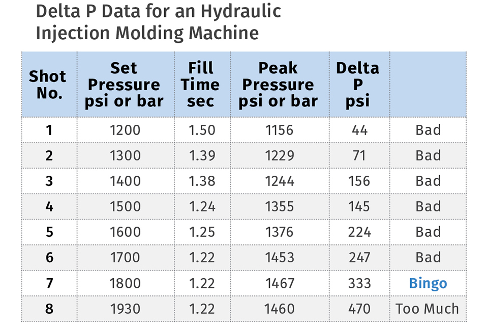
- Record first-stage set pressure limit, fill time and peak pressure during injection. See accompanying table.
- Once you are running pressure-limited, increase first-stage pressure limit by 100 to 200 psi (7–14 bar) for hydraulic machines, or 500 to 1000 psi (35 – 70 bar) for electric machines.
- Repeat Step 8 until two criteria are met as you increase first-stage set or allowable pressure: A) Fill time stops dropping and becomes constant; and B) peak pressure stops trending up. That’s the appropriate Delta P for that particular machine. Please note that you may not find the correct Delta P, as the machine may not have enough injection pressure available to establish a Delta P. Reminder: For each shot, make sure you are making a short shot with some cushion!
Develop a data table similar to the one here. The shot labeled “Bingo” shows the minimum Delta P required for this hydraulic machine. Note that the 333 hydraulic pressure is significantly higher than the typical 10% higher often recommended. In this case it’s well over 25%. Moreover, do not get into the habit of ignoring this Delta P by just setting the set or allowable pressure to the machine’s maximum. Why? If set pressure is at the maximum or significantly higher than peak pressure on a multicavity tool, and a cavity accidentally plugs due to a cold slug…what will happen? The machine will overpack the remaining cavities, flash a slide, or at a minimum you will have flash to clean up.
Once you have established the required Delta P for a machine, put a note on the controller stating what it is. This makes it easier for the processors. Expecting them to remember Delta Ps for 10, 20 or more machines is insane. Also, you have to check the load-compensation circuit: Check out the end of a column I wrote in 2010 (short.ptonline.com/evaluate).
Bottom line: Keep fill time constant to run identical parts. Accomplish this using an appropriate Delta P and having a working load-compensation circuit. Let the machine do the adjusting to keep fill time the same. It is designed to do this, but the machine must be set up properly.
ABOUT THE AUTHOR: John Bozzelli is the founder of Injection Molding Solutions (Scientific Molding) in Midland, Mich., a provider of training and consulting services to injection molders, including LIMS, and other specialties. Contact john@scientificmolding.com; scientificmolding.com.
Related Content

A Simpler Way to Calculate Shot Size vs. Barrel Capacity
Let’s take another look at this seemingly dull but oh-so-crucial topic.
Read More
How to Select the Right Tool Steel for Mold Cavities
With cavity steel or alloy selection there are many variables that can dictate the best option.
Read More
The Importance of Melt & Mold Temperature
Molders should realize how significantly process conditions can influence the final properties of the part.
Read More
How to Get Rid of Bubbles in Injection Molding
First find out if they are the result of trapped gas or a vacuum void. Then follow these steps to get rid of them.
Read MoreRead Next

Part 1: The Importance of Consistent Fill Time
To make identical parts, you need to keep fill time constant. Here’s why.
Read More
How Polymer Melts in Single-Screw Extruders
Understanding how polymer melts in a single-screw extruder could help you optimize your screw design to eliminate defect-causing solid polymer fragments.
Read More
Understanding Melting in Single-Screw Extruders
You can better visualize the melting process by “flipping” the observation point so that the barrel appears to be turning clockwise around a stationary screw.
Read More