
Tricks of the Trade on RTOs and RSOs
The more you know about these runner diverters and shutoffs, the more you’ll use them. Here’s how to put them to work in your mold..

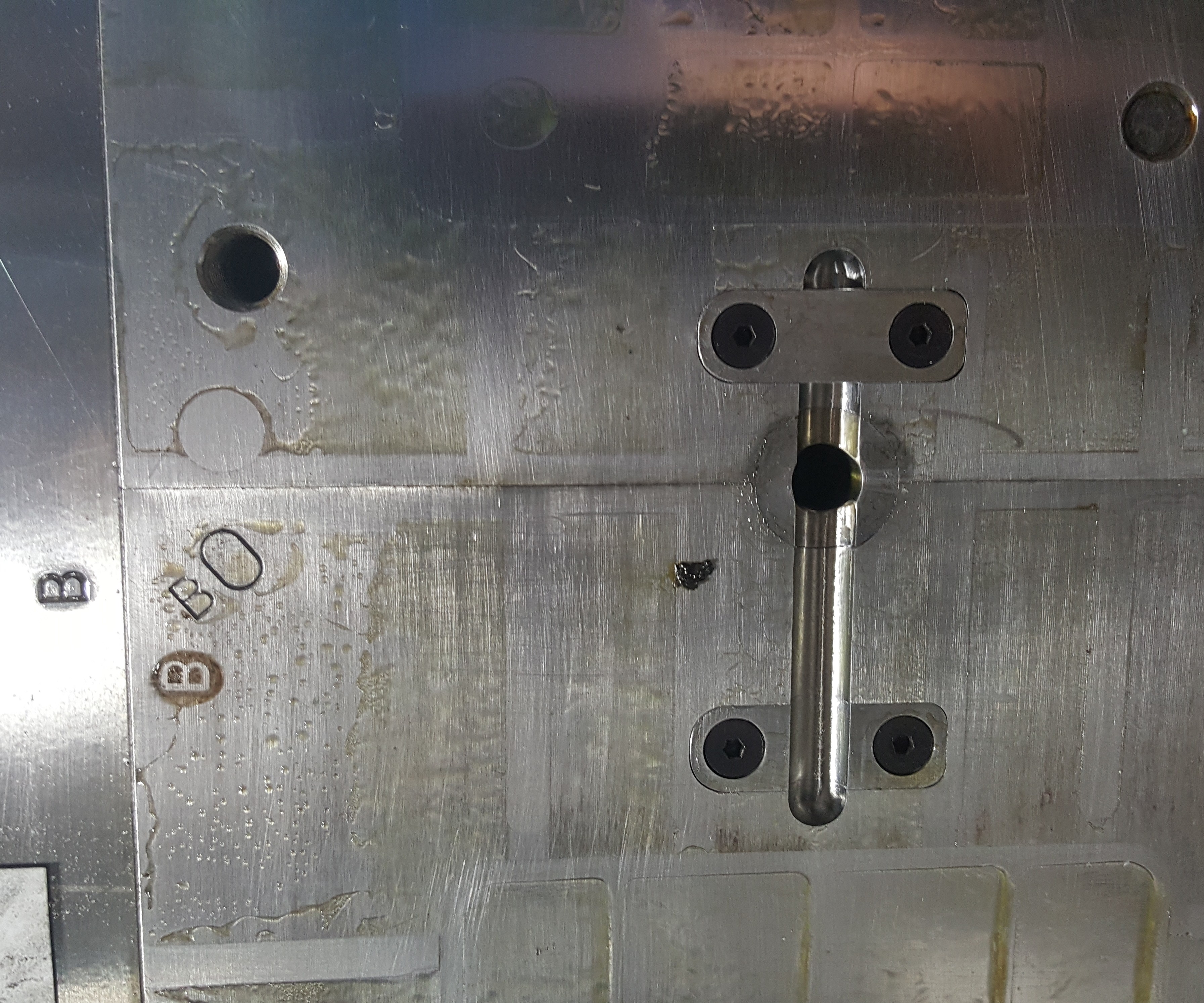
FIG 1 A basic RSO blocks or diverts the flow of material.
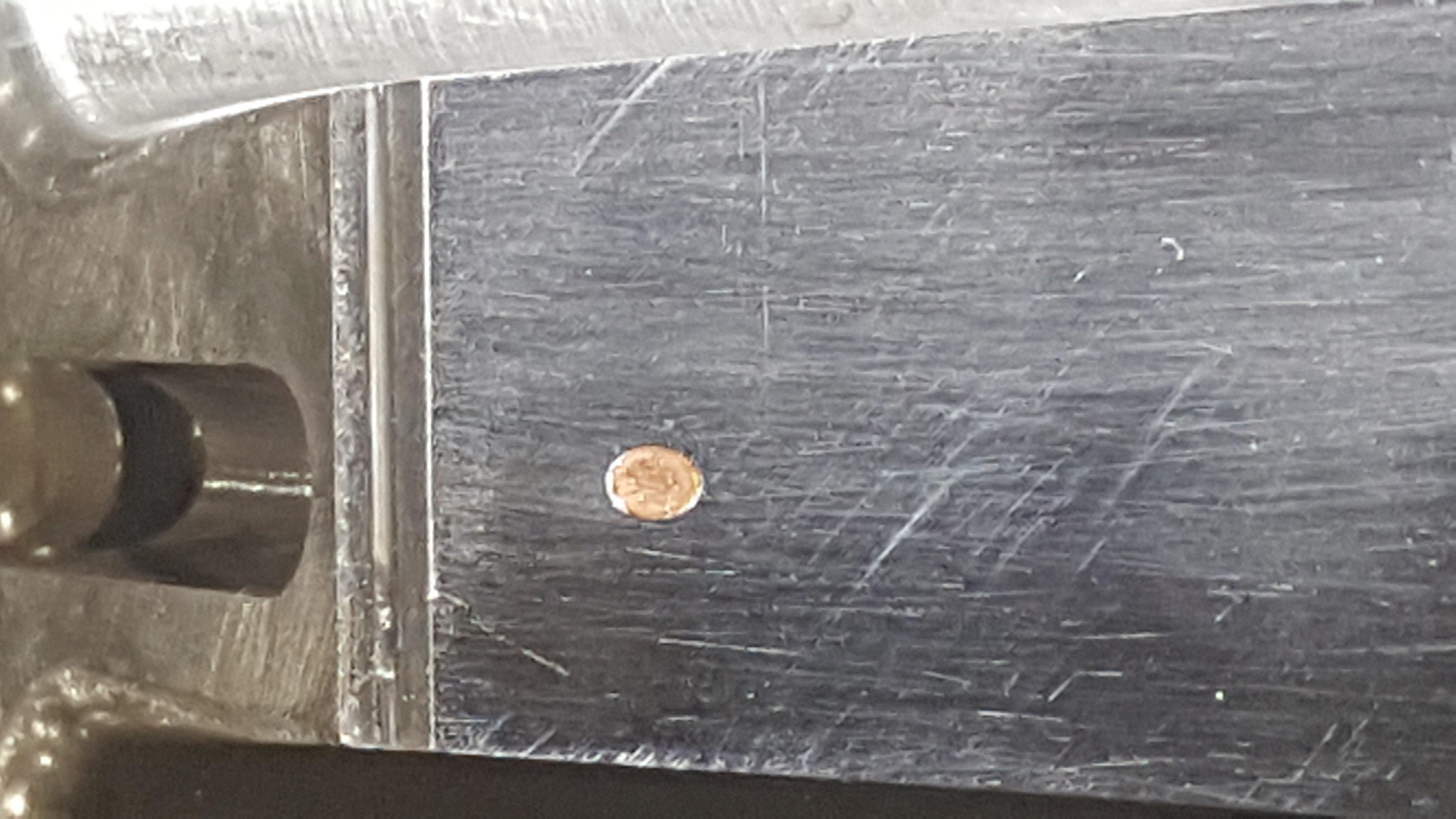
FIG 2a Subgates blocked with copper.
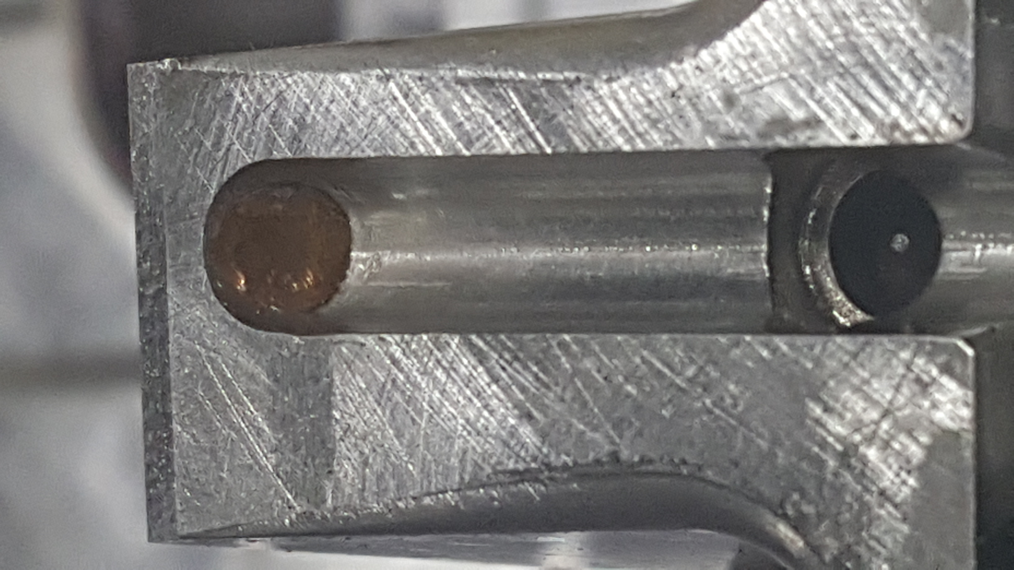
FIG 2b
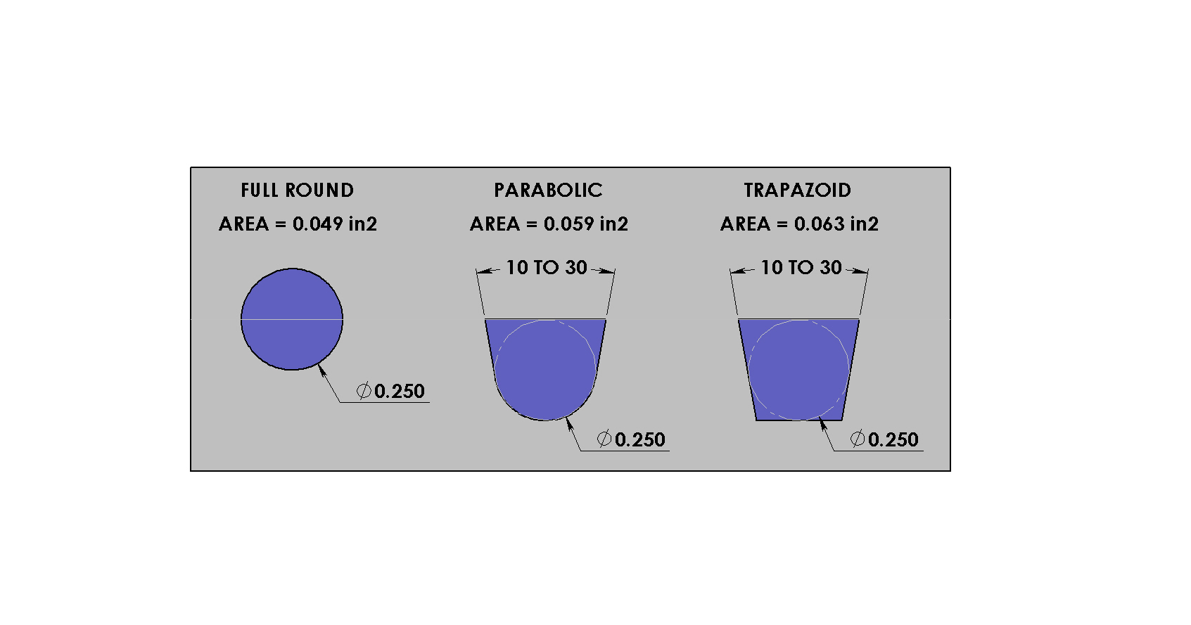
FIG 3 Flow areas of different types of cold-runner shapes.
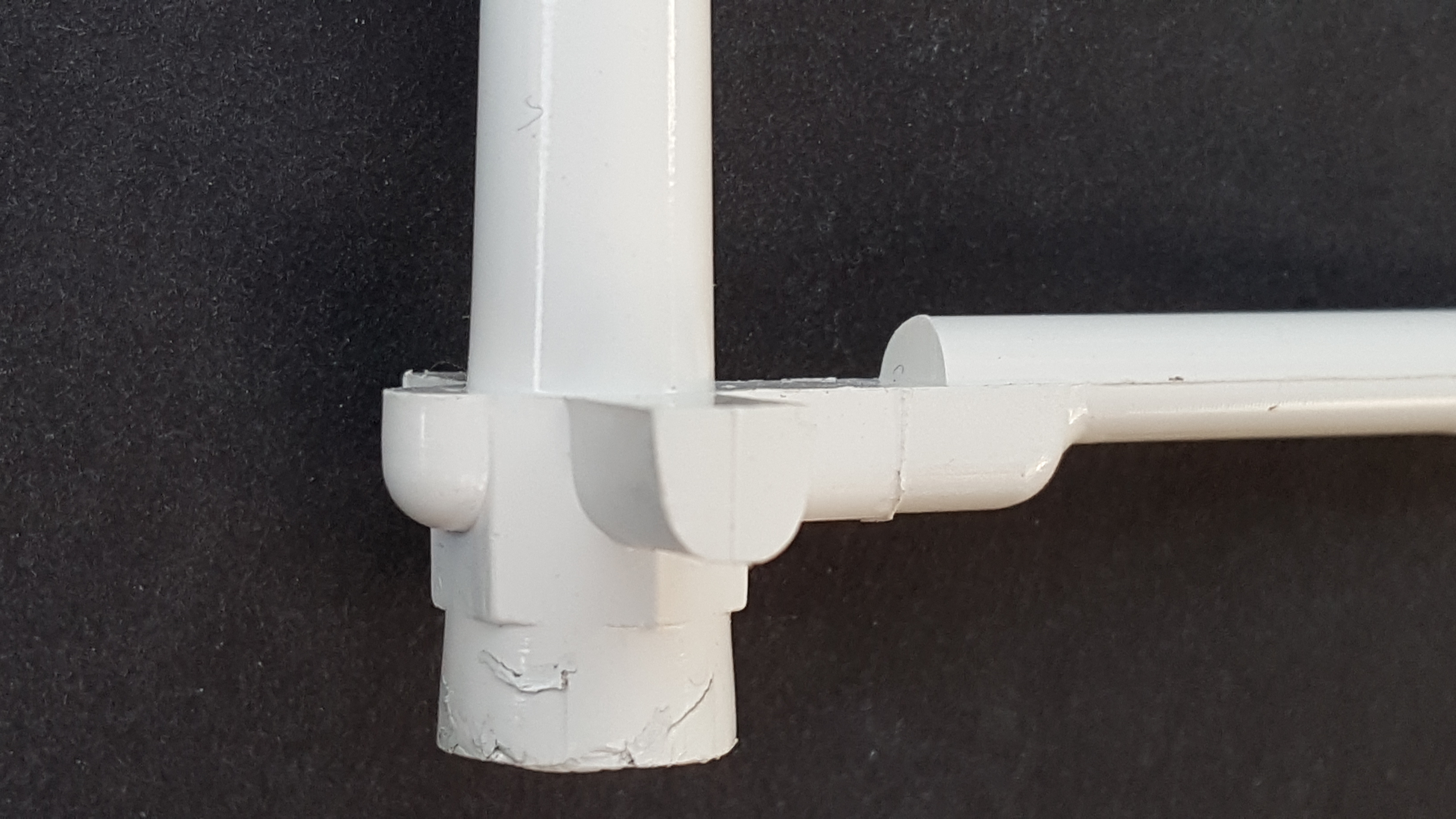
FIG 4 A parabolic RTO feeding a full-round runner.
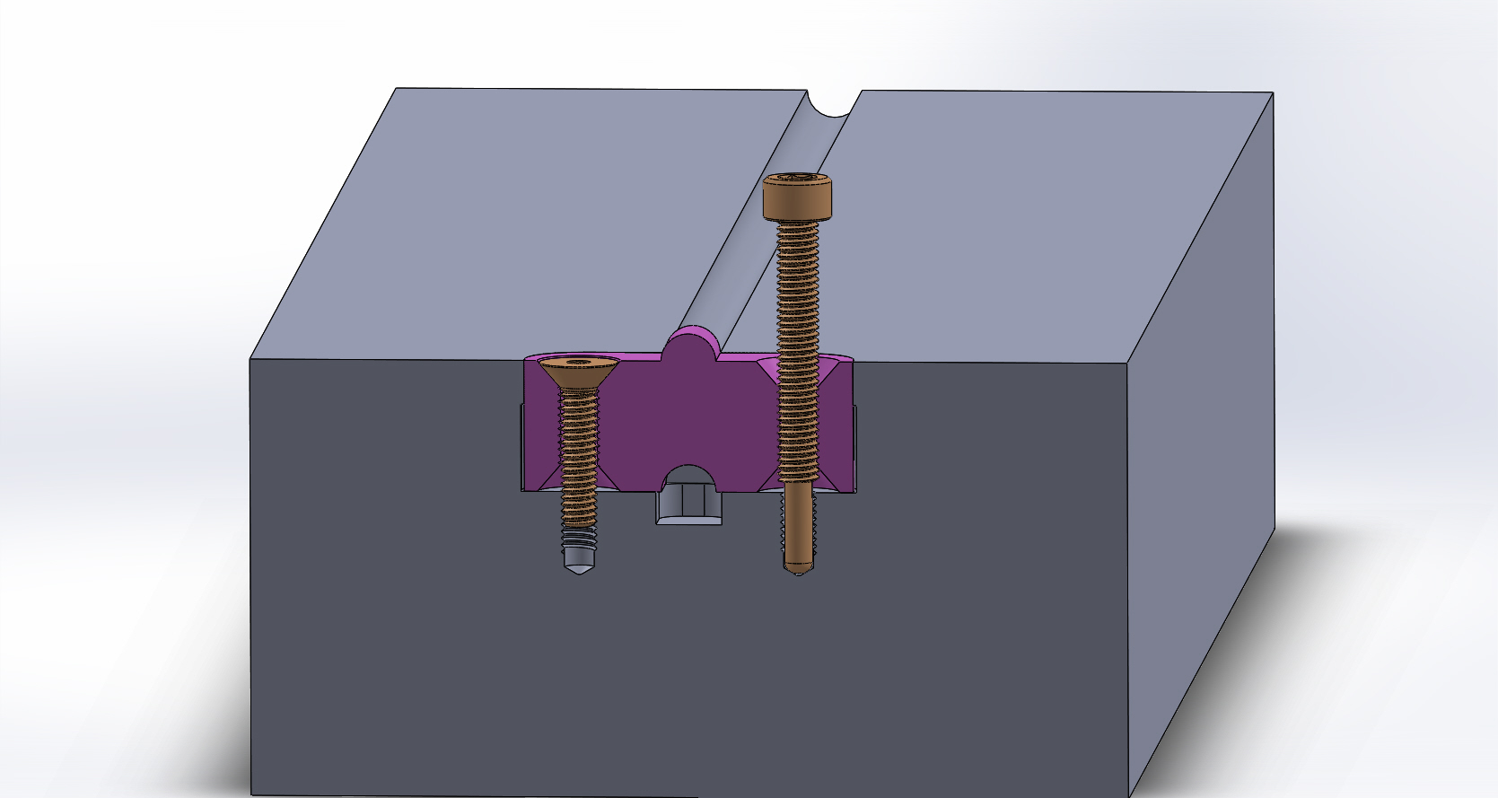
FIG 5 A one-piece RSO for a full-round runner. The jack-screw on the right is used to remove the RSO.


Let’s start by defining what an RTO and an RSO is. An RTO is a Runner Turn-Off. It is a cylindrical-shaped mold component that can be rotated to prevent the flow of molten material from continuing down its path, diverts it to a different path, or both. RTOs are often located opposite a sprue bushing, but they are also commonly located at the intersection of a runner branch.
An RTO is a specific type of the more generic Runner Shut-Off, or RSO. An RSO can be round, square, rectangular, or any shape imaginable. If it blocks or diverts the flow of material, it’s an RSO (see Fig. 1). It can be a small insert with a portion of a runner cut into it. Flip it over and it blocks the flow of material. Or it can be extremely large. Say, for example, you had two MUD inserts in an “H”-Frame and one of the inserts had a problem, or you just wanted to mold one of the inserts. You could rotate the unwanted insert 180°, which effectively makes that entire cavity and core set an RSO—preventing the flow of material from entering it.


RSOs are usually used in family molds, because it is common not to need all the different parts during every production run. Molding unneeded parts, and then throwing them out or grinding them up is anything but efficient. RSOs are typically used in two-plate molds, but function equally as well in three-plate molds.
One advantage to RSOs is that they eliminate the need to use unhealthy methods of blocking off a gate. How many of you have ever pounded a piece of brass, copper, aluminum or electrical solder into a sub-gate hole? (See Fig. 2.) Maybe you prefer to apply cyanoacrylate (aka Krazy-Glue) onto a small portion of a molded part and strategically place it on the core near the gate. Or maybe you go as far as leaving an unwanted part in the cavity and either removing the ejector pins to that part, or drilling holes in the part where the ejector pins are located. These methods are not foolproof; they take time to install or perform and can cause damage to the mold—particularly during removal.
Before I discuss other types of RSO designs, let’s briefly review the different types of cold-runner shapes. There are only three types that should even be considered for injection molds. In order of priority, they are: full round, parabolic and trapezoidal. Full-round runners are the most efficient. They have the lowest ratio of cross-sectional perimeter to cross-sectional area. If you are running only virgin material, full-round runners are the way to go (Fig. 3).
However, there are advantages and disadvantages to parabolic and trapezoidal-shaped runners. These runner shapes need only to be machined into one side of the parting line and they have a lower pressure drop than a full-round runner. But depending on the included angle, they can use 20% to 35% more material than a full-round runner, which potentially can extend the molding cycle time—especially if the runner is removed by a robot or picker. Parabolic and trapezoidal runners can also cause aesthetic issues with certain types of gates, which is a subject for a future article.
If you have a parabolic or a trapezoidal cold-runner design, you only need one RSO. If you have a full-round runner, you will need a second, mating RSO on the opposing side of the mold. But you can be a little creative and avoid having to use two RSO’s by doing either one of two things. First, you can have a parabolic or trapezoidal runner cut into the RSO, which feeds a full-round runner, but you need to make sure of two critical design features. The cross-sectional area of the trapezoidal section must be equal to or greater than that of the full-round runner, and the amount of overlap must be sufficient—usually 1.25 to 1.5 times the cross-sectional area. Otherwise, you will be restricting the material flow, which causes an undesirable spike in injection pressure. As long as the material isn’t shear sensitive, this design can save a few dollars—and a few headaches.
The other thing you can do is have an RSO with a protrusion extending into the opposing side of the mold to shut off that half of the flow channel (Fig 5). In this design, #8-32 flat-head cap screws are used to secure the RSO in a pocket in the mold base. The countersinks on both sides of the RSO enable you to flip it over and re-secure it to the mold base. The half-round cutout on the bottom of the RSO has the same radius as the runner channel, which when flipped over, allows for uninterrupted material flow. The small inside diameter between both sets of countersinks is drilled with a #19 (0.166-in.) drill and then tapped with a #10-32 thread. The #19 drill is required to clear the outside diameter of the #8 screws. The reason for this #10-32 thread is so a pair of #10-32 socket-head cap screws can be used to easily remove the RSO from its pocket. The ends of the #10 screws are turned down to 0.130 in. diam. This diameter is smaller than the root diameter of the #8-32 thread to prevent any damage to the start of the threads in the pocket. The length of the threaded portion is equal to or greater than two times the height of the RSO. This modified screw is called a jack screw. It’s a good idea to mount these jack screws directly to the mold. One method is to drill and tap two holes in any available location, such as an ejector-housing rail or a clamp plate. This eliminates the need to spend an untold amount of time having to hunt for them later.
Even though this RSO is for a full-round runner, it can also be configured for a parabolic or trapezoidal runner. This type of RSO can be mounted on either side of the parting line, which can be very handy if a water line or other obstruction is in the way. Lastly, since mating mold components usually “seat” themselves, it is a good idea to orient the RSO. One method to ensure the RSO is always in the proper orientation is to machine the two corners on one end of the insert with a different radius than the opposing two corners. For example, if one end had a pair of 1/8-in. radii and the opposite end had ¼-in. radii, there is only one possible way the RSO can be installed in the pocket in the mold. If you look closely at Fig. 1, you can see that is exactly how those RSOs were machined.
ABOUT THE AUTHOR: Jim Fattori is a third-generation injection molder with more than 40 years of molding experience. He is the founder of Injection Mold Consulting LLC, and is also a project engineer for a large, multi-plant molder in New Jersey. Contact jim@injectionmoldconsulting.com; injectionmoldconsulting.com.


Related Content

Density & Molecular Weight in Polyethylene
This so-called 'commodity' material is actually quite complex, making selecting the right type a challenge.
Read More
The Effects of Temperature
The polymers we work with follow the same principles as the body: the hotter the environment becomes, the less performance we can expect.
Read More
How to Set Barrel Zone Temps in Injection Molding
Start by picking a target melt temperature, and double-check data sheets for the resin supplier’s recommendations. Now for the rest...
Read More
How to Get Rid of Bubbles in Injection Molding
First find out if they are the result of trapped gas or a vacuum void. Then follow these steps to get rid of them.
Read MoreRead Next

Understanding Melting in Single-Screw Extruders
You can better visualize the melting process by “flipping” the observation point so that the barrel appears to be turning clockwise around a stationary screw.
Read More
How Polymer Melts in Single-Screw Extruders
Understanding how polymer melts in a single-screw extruder could help you optimize your screw design to eliminate defect-causing solid polymer fragments.
Read More