
TOOLING: Designing the Tool for the Material
To design a mold for the widest processing window and the fewest problems, start by considering the conditions imposed by the material being run.
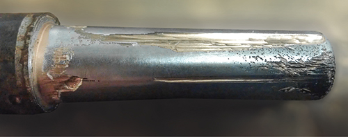
This badly eroded mold core is testimony to the abrasiveness of glass-filled compounds. Special steels, coatings, and surface hardening can combat this.
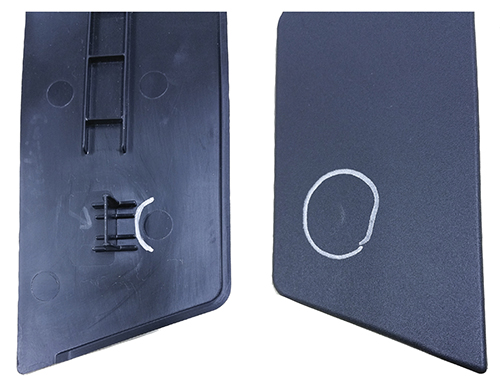
PP is an example of a material that is very susceptible to pin push or ejector marks. In this example, pin push occurs with an ejector placed next to a rib detail. The ejector force required to push the ribs out of the cavity contributed to pin push, which is easily visible on the front side of the part.
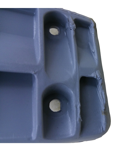
An example of mold erosion due to gas traps. Attention to adequate venting is always important but is especially critical with glass-filled materials, which tend to be more gassy.


In most plants, the tool shop and the molding shop are not connected closely enough. In my own career, I made the transition from the tooling side to the injection molding side, which gave me a perspective different from most of my colleagues. Whenever I was involved with troubleshooting an issue, the tool was always on the top of my list to dig into. I never put the machine or process in front of the tool.
My focus now is to provide the largest molding process window possible, using the tool whenever possible to resolve issues. Whenever you try to “process around” an issue, your process window becomes smaller. With a smaller processing window you are at higher risk for quality problems.


There are many things to consider when designing an injection tool—the volume of parts expected to be molded, plastic being used, inserts, cycle time expectations, part quality expectations, maintenance, and ease of assembly and disassembly. Among all these variables, the first and perhaps most important is the material to be run.
Start by understanding the issues different plastics can create. Some issues you will need to design around, depending on the plastic, are pin push, flash points, erosion, cooling, splay, venting, gloss, and surface finishes that contribute to sticking.
Polypropylene, for example, is very susceptible to pin push (ejector marks) where other materials are not. This requires more focus on ejection with pins and lifters. Changing from a 0.250-in.-diam. ejector pin to a 0.375-in.-diam. pin more than the doubles the ejection surface area. But even more important is to focus on pushing on the details of the part versus nominal wall stock. If you put an ejector pin next to a rib detail you will be stressing the part while trying to pull the plastic out of a rib or detail. But if you put the ejector pin or blade on the bottom of the detail you will have much less tendency toward pin push or stress marks. This will also allow venting in areas where gas traps can contribute to splay and erosion. In most cases, PP is not considered a material that will erode steel, but I have been involved with some significant erosion on tools running PP from severe gas traps.
TOOL DESIGN FOR GLASS-FILLED MATERIALS
When designing a mold that will run a glass-filled (GF) material, more attention to erosion, venting, and cooling are necessary. These issues are important with all materials, but GF materials require design changes to address them. Most of my experience with GF materials is with nylon, PP, and Noryl (PPE alloy). Erosion can be addressed with the tool steel, coatings, and surface hardening. The volume of parts expected to run will also affect the choice of steel to minimize erosion. Hardened tool steels such as H-13, S-7, and stainless steel are preferred for tools that will run a high volume of parts, but they do increase the cost of the tool. P-20 tool steels can have coatings applied or have the surface hardened to minimize erosion while keeping the initial cost down. But hardened tool steels allow a quicker turnaround time and lower cost when it comes to repairing eventual erosion and other damage. When you have coatings or surface hardening, the repair can take much longer and the costs will be higher.
Tool erosion typically comes from two different causes—the glass content and lack of venting. The tool steel, coating, or surface treatment will address the erosion from the glass content. But with GF materials, venting is much more critical to address erosion because they are typically more gassy. Venting ribs, details, knit lines, and the parting line at any point where there is a gas trap is critical.
During the initial tool design, it can be difficult to know where these gas traps will occur, but flow simulation software has gotten better at predicting them. Flow simulation (mold analysis) is an added cost up front but it can reduce the amount of rework on venting after the tool is built. (Venting is a major subject in itself and a weak area in the industry.)
MORE COOLING, LESS STICKING
Cooling is also more critical with GF materials, especially nylons and PPE alloys, to address cycle time and sticking issues. If I ever have sprue sticking with GF materials, it typically results from insufficient cooling in the sprue area. (On the other hand, PP at times actually sticks less as the tool warms up.) You will need to be more creative on tools running GF materials in finding ways to add cooling in certain areas to reduce cycle times, part blowouts, and other quality issues. We have probably all heard someone say, ‘We can’t get water in there,’ but where there’s a will there’s a way.
TOO SMOOTH CAN BE TROUBLE
Tool and part surface finishes can also contribute to molding. Most of the time when there is a sticking problem, tool shops will polish the mold surface. With some materials this will make things even worse. Most TPU, TPE, and TPO resins prefer a blasted or textured surface, but depending on the durameter that is not always the case. Some react better to an aluminum oxide finish, some to glass bead, and some to a draw polish.
PP is another material that will stick to a highly polished surface—it acts like a suction cup. I have found a 320 or 400 paper draw polish is best in this case. PC can also stick to highly polished surfaces. There are also some coatings that can be applied to assist with release.
Gating and runner sizes are areas that are material specific also. I have found that the industry does not have really any good standards when it comes to this. There are so many variables with regard to flow length and wall thickness that can impact gate and runner sizes. Some materials prefer smaller gates to produce shear for easier flow, and some filled materials need larger gates. As noted in last month’s column, the gate geometry alone can have a huge impact on scrap and cycle time.
There is also a lot of waste in the industry due to excessive runner sizes. I have found this is an area that lacks research and is not susceptible to easy generalization. I hope to provide more insight on this from my own studies at a later date.


Related Content

How to Set Barrel Zone Temps in Injection Molding
Start by picking a target melt temperature, and double-check data sheets for the resin supplier’s recommendations. Now for the rest...
Read More
Tunnel Gates for Mold Designers, Part 1
Of all the gate types, tunnel gates are the most misunderstood. Here’s what you need to know to choose the best design for your application.
Read More
Know Your Options in Injection Machine Nozzles
Improvements in nozzle design in recent years overcome some of the limitations of previous filter, mixing, and shut-off nozzles.
Read More
The Effects of Temperature
The polymers we work with follow the same principles as the body: the hotter the environment becomes, the less performance we can expect.
Read MoreRead Next
Why (and What) You Need to Dry
Other than polyolefins, almost every other polymer exhibits some level of polarity and therefore can absorb a certain amount of moisture from the atmosphere. Here’s a look at some of these materials, and what needs to be done to dry them.
Read More
Troubleshooting Screw and Barrel Wear in Extrusion
Extruder screws and barrels will wear over time. If you are seeing a reduction in specific rate and higher discharge temperatures, wear is the likely culprit.
Read More
Understanding Melting in Single-Screw Extruders
You can better visualize the melting process by “flipping” the observation point so that the barrel appears to be turning clockwise around a stationary screw.
Read More