
Tooling: Know the Basics of Sprue-Puller Design
Sprue-puller designs are quite varied, and there are no firm rules to follow. But here are some important cautions and caveats to keep in mind.

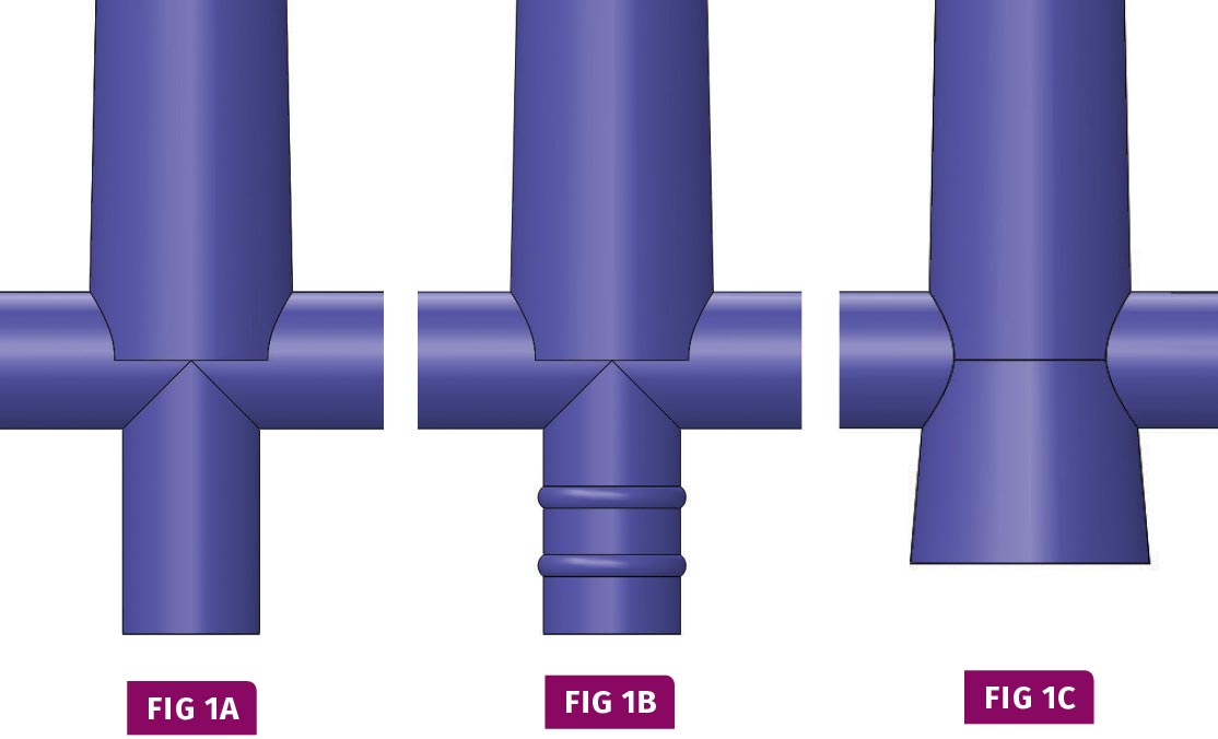
Typical sprue pullers for prototype and low-production molds.
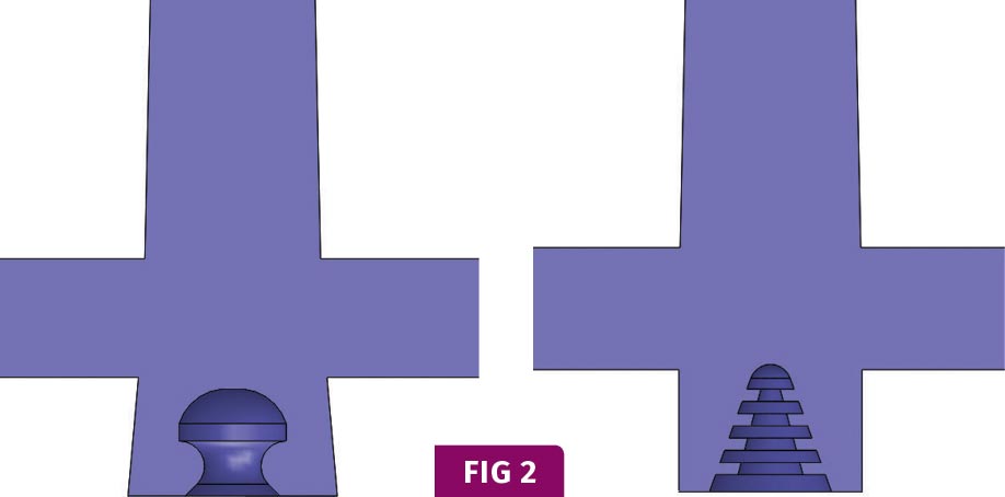
“Lollipop” and “Christmas Tree” or “Pine Tree” sprue-puller designs are less common, because it is difficult—and critical— to determine the proper amount of undercut.
Accelerated wear on an ejector pin and sleeve is often due to the pin and sleeve having the same diameter as the non-drafted sprue puller.
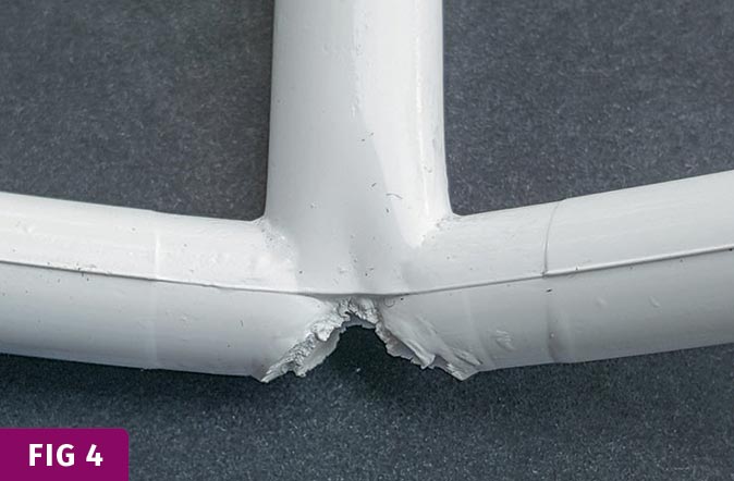
Sprue puller separated from the runner—as shown here—can result in the sprue remaining in the bushing. Prevention involves eliminating sharp corners between the runner and sprue.
Small changes to the basic reverse-taper sprue puller (Fig. 1C) make a big difference in its performance. Note the radius at the bottom edge of the undercut and the boss added to its base.
Short and long sprue pullers with the same amount of undercut. Moral of the story: The amount of reverse taper is meaningless without considering its length.
An excessive amount of undercut in a sprue puller can cause tearing and flaking.
Sprue pullers can have multiple undercuts. Shown here, one proactive, one reactive.
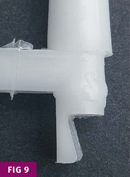
A molded pin with a Z-Pin type sprue puller, recommended only for elastomeric materials.


A sprue puller is one of many design requirements for most two-plate, cold-runner molds in order for it to run fully automatic. It is typically located directly opposite the shank end of the sprue bushing and its purpose is, as the name implies, to pull the molded sprue out of its bushing. The puller then retains the sprue during the mold-opening stroke and up until the time it is ejected.
There are no hard-and-fast rules for sprue-puller design, and everyone has their own preferences. This article will address many of the intricacies of sprue pullers—their advantages and disadvantages—to help you build a better mold.


Sprue pullers can be made in any number of design variations. Some typical designs for prototype or low-production molds are shown in Figs. 1A, 1B, and 1C. Figure 1C is a “no-frills,” reverse-tapered (also called back-drafted or re-entrant-angled), undercut design. These are some of the least expensive designs to manufacure and are usually fine—as long as you don’t mind an occasional sprue sticking in the bushing, a parting line peppered with damaging plastic flakes, an extended cycle time, or premature wear of the ejector system.
Other variations, such as the “Lollipop” or “Christmas Tree” (also called “Pine Tree”), are less common—and for good reason (Fig. 2). Determining the proper amount of undercut for these pullers is extremely difficult, and the window between having sufficient holding force to pull out the molded sprue, versus the undercut shearing off and leaving flakes on the parting line, is extremely narrow. I have read that the lollipop design is recommended when using robotics. There are several methods for facilitating robotic extraction of a runner—this isn’t one of them.
No matter what the design, the puller, sprue, runner, and parts are typically ejected at the same time. But on occasion, a two-stage ejection system is used to either accelerate or delay the ejection of the runner system to facilitate part or runner removal.
Almost all sprue-puller designs use an ejector pin at the base of the puller. There is no need to vent this ejector pin, since there is not a lot of trapped air to compress and burn. In fact, venting the pin may accelerate its wear and corrosion, which will eventually lead to “down-flash.”
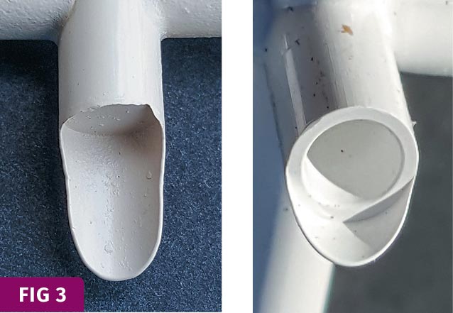
If you have a straight-sided sprue puller (or any straight-sided boss on a runner or a part), use an ejector pin that is slightly smaller than the diameter of the puller (Fig. 3). Since thermoplastic material exhibits fountain flow, the last place to fill will be in the blind radial corner of the puller, not at the edge of the pin. This will help reduce the corrosive wear on the side of the pin. The same is true for ejector sleeves.
In the August Tooling Know-How article, I discussed how adding some radii to eliminate the sharp corners between the runner and the sprue can help prevent the runner from cracking. The same is true for the intersection of the sprue puller and the runner, regardless whether the runner is a full-round or a parabolic design machined into either the A or B plate. If the sprue puller is torn from the runner when the mold opens (Fig. 4), the molded sprue might remain in the bushing. Since the molding machine cannot detect a stuck sprue, at the start of the next cycle things are going to get messy.
The sprue puller in Fig. 1C has a sharp edge at its base, or major diameter of the reverse taper. This edge will surely abrade during ejection and probably leave damaging flakes of material on the parting line. To minimize this malady, the bottom edge of this undercut should be radiused (Fig. 5). As just mentioned, it is equally important to add a radius to the minor diameter where it intersects the runner. Instead of having a sharp edge pushing through and scraping against another sharp edge, you now have a radius rubbing against a radius.
Another design improvement to the sprue puller in Fig. 1C is to add a boss at its base (Fig. 5). The diameter of the boss should be at least 0.010 in. smaller than the minor diameter of the tapered puller near the parting line, and its depth or length should be 0.050 to 0.300 in. Eject the sprue puller with a pin about 1/16 in. smaller than the diameter of this boss.
There are three reasons for adding a boss to a sprue puller coupled with a reduced-diameter ejector pin:
- To help the puller collapse inward during ejection and reduce the chance of shaving plastic;
- To reduce the formation of “down-flash” on the sides of the ejector pin;
- To reduce the chance of the ejector pin pushing into the sprue puller, which is often still soft or molten inside.
When an ejector pin pushes into a soft sprue puller, it can cause the puller to wrap around and hang on to the pin. This can cause the runner system to “go for a ride.” Multiple ejector pulses are then required to dislodge the sprue puller from the pin, and that extends the cycle time. Furthermore, two ejector pulses doubles the amount of wear on the ejector system. Three pulses triples the amount of wear—and so on. Remember that the next time you walk past a molding machine and hear a repetitive click-clack, click- clack, click-clack.
Some mold-component suppliers include a “standard”-size sprue-puller ejector pin in their mold bases. Nine times out of 10, the size of these ejector pins hinders your inclination to design a better mold. Order the mold base without this pin and install the ideal size hole after the mold design is finalized.
So how much of a reverse taper should a sprue puller have? Many books, articles, and technical literature from material suppliers suggest using 3° to 5° of taper per side. That’s totally useless information if they don’t specify the length. For example, if one sprue puller is machined at a re-entrant angle of 5° per side over 0.171 in., and another is machined at
just 1° per side over 0.859 in., they both will have the same 0.015 in. per side
of undercut (Fig. 6). When designing the sprue puller, focus on how much undercut is needed, not on which angle to use, because the amount of undercut is what primarily controls the holding force.
There’s no law that says you can only have a single undercut on the sprue puller. In fact, pullers with multiple smaller pullers is an excellent idea for very rigid, low-shrink materials that tend to shave or flake when stripped out of a deeper, more aggressive undercut (Fig. 8). This approach allows the depth of each undercut to be shallower, but maintains the necessary holding force. It’s also very clean looking, as opposed to someone hacking up a mold with a ball mill and a Dremel.
The amount of undercut required to pull a molded sprue out of its bushing depends on no less than six different variables, many of which are not often taken into consideration during the mold-design stage.
- The diameter of the puller;
- The cycle time;
- The amount of cooling near the puller;
- The amount and length of time of pack and hold pressure;
- The condition of the sprue bushing and the machine nozzle tip;
- The type of material being molded.
The diameter of the puller, the mold’s cycle time, and the amount of cooling near the puller are all interrelated, because they determine whether or not the sprue puller is sufficiently solidified when the mold opens. If the mass is large, the cycle short, and the cooling poor, the sprue puller will be soft and have very little holding force. These conditions require a larger amount of undercut.
A large-diameter sprue puller will have more mass, which makes it shrink more. That causes two problems: The more it shrinks, the less the amount of effective undercut.
A large mass will also shrink away from the adjoining steel, which reduces the rate of heat transfer and increases the time required to solidify. It is not uncommon for the center of a sprue puller to be completely molten with a semi-solidified shell around it. This reduced structural integrity can lead to the sprue pulling the puller out of the moving half of the mold. To compensate for this problem, processors will extend the pack and hold time well beyond the time the gate freezes.
The sprue puller not only has to overcome the forces holding the sprue in its bushing, it also has the added resistance of any solidified portion of material in the machine nozzle tip, as well as any flash or mismatch between the nozzle tip and the bushing’s nozzle seat. Using sprue break to solve the problem is not a good idea. These additional forces can actually
be greater than the force required to remove the sprue itself. Determining the required amount of undercut is virtually impossible to calculate or predict. You have to use your best judgment, combined with the opinion of an experienced molder. It is not uncommon to tweak the amount of undercut after the initial mold sampling or first production run. Therefore, it is better to err on the steel-safe side of caution—i.e., less undercut.
Materials with shrinkage factors of 0.015 in./in., such as many unfilled nylons or polypropylenes, require a greater amount of undercut to compensate for the material
shrinking away from the side walls of the mold. Materials with a shrinkage factor of 0.004 in./in. or less, such as highly filled amor- phous materials, need less of an undercut to be effective. Materials with hardness values above approximately 115 Rockwell R, or 75 Rockwell M, need only a small amount of undercut. Too much undercut for these materials usually results in damaging flakes on the parting line.
Softer materials, such as polyethylene, can flex and compress more than rigid materials, and therefore can have a more aggressive undercut without many issues. But very soft materials, such as elastomers, need a tremendous amount of undercut. In fact, if the durometer of the material is extremely low, no amount of undercut will hold the sprue puller in place. These types of materials usually require either a Lollipop sprue puller or what is known as a Z-pin (Fig. 9).
I recommend that Z-Pins should only be used for elastomeric materials because they have several inherent design flaws:
- They are not very good at trapping the cold slug from the nozzle tip, unless they are positioned sufficiently below the runner;
- They have to be keyed or aligned so as not to cause the runner to hang up;
- They have several sharp edges, which are both stress concentrators and a safety hazard when working on the mold;
- They tend to develop flash faster, because the injection pressure pushes against the side of the pin.
- They cannot be “stepped” to prevent premature flashing down the side of the ejector pin.
ABOUT THE AUTHOR: Jim Fattori is a third-generation injection molder with more than 40 years of molding experience. He is the founder of Injection Mold Consulting LLC, and is also a project engineer for a large, multi-plant molder in New Jersey. Contact jim@injectionmoldconsulting.com; injectionmoldconsulting.com.


Related Content

How to Mount an Injection Mold
Five industry pros with more than 200 years of combined molding experience provide step-by-step best practices on mounting a mold in a horizontal injection molding machine.
Read More
Why Shoulder Bolts Are Too Important to Ignore (Part 1)
These humble but essential fasteners used in injection molds are known by various names and used for a number of purposes.
Read More
What You Need to Know About Leader Pins and Bushings
There’s a lot more to these humble but essential mold components than you might suspect. Following the author’s tips could save much time, money and frustration.
Read More
How to Optimize Pack & Hold Times for Hot-Runner & Valve-Gated Molds
Applying a scientific method to what is typically a trial-and-error process. Part 2 of 2.
Read MoreRead Next

Tooling: Reducing the Mass In Sprue Bushings
Important and frequently overlooked details of sprue-bushing design can improve the process and profits for an injection mold.
Read More
Why (and What) You Need to Dry
Other than polyolefins, almost every other polymer exhibits some level of polarity and therefore can absorb a certain amount of moisture from the atmosphere. Here’s a look at some of these materials, and what needs to be done to dry them.
Read More
Advanced Recycling: Beyond Pyrolysis
Consumer-product brand owners increasingly see advanced chemical recycling as a necessary complement to mechanical recycling if they are to meet ambitious goals for a circular economy in the next decade. Dozens of technology providers are developing new technologies to overcome the limitations of existing pyrolysis methods and to commercialize various alternative approaches to chemical recycling of plastics.
Read More