Understanding Solids-Bed Breakup in Barrier Screws
Barrier screws all but eliminate problems associated with solids-bed breakup. But if they do occur, tremendous pressures can develop, causing screw wear.
.jpg;width=70;height=70;mode=crop;format=webp)
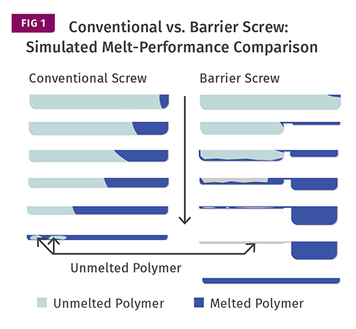
Melting in a conventional vs. barrier-flighted screw is visualized as if the screw flight were “unwrapped” into a continuous channel. The different views are “slices” across that channel along the screw in the direction of flow, shown by the arrow pointing downward. The channel depth decreases as you travel down the screw. In the ideal state, at the end of the barrier screw there is only melted polymer, but the conventional screw still has some solid lumps.
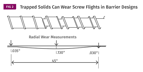
A tremendous amount of force is generated when a solid plug fills the end of the solids channel in a barrier screw. On this 8-in. barrier screw, the wear pattern indicated a force of about 350,000 lb over 45 in. caused the shaft to bend 0.100 in.

One of the advantages of barrier screws is that for the most part they eliminate the problems associated with solids-bed breakup that are typical in conventionally flighted screws. Many conventional screws have to rely on restrictive mixing sections to complete the melting process because solids conveyed into the metering section are difficult to melt.
With barrier screws this is essentially eliminated, as solids are trapped in the solids channel until they pass over the barrier and/or a high-shear section at the end of the barrier section. As a result, solids are completely melted by the time they reach the metering section (see Fig. 1). This ensures that a more thermally homogeneous melt exits the screw without need for a mixing section.


That said, solids-bed breakup can still be a factor in designing barrier screws. If the polymer in the solids channel somehow does manage to break up, it similarly becomes much more difficult to melt because it again becomes dependent on conduction for melting rather than on shear or viscous dissipation. Since polymers are effectively insulators, conductive melting is very inefficient and requires a high temperature differential between the surrounding melt and the unmelted portion to have any efficiency at all.
Crystalline polymers, particularly polyolefins, are inherently much more susceptible to this issue because they do not appreciably soften as they are melted and require a higher differential between the surrounding melt and remaining solid to overcome the heat of fusion using conductive heating.
Most often, solids-bed breakup in barrier screws seems to occur when the compression section is too gradual. This allows the solid bed to be undermined by melt, destroying its structural integrity. In a conventional screw, the solids that have broken up are simply conveyed forward, creating no pressure spike.
But in a barrier design, they remain trapped in the solids channel. As the solids channel cross-section is reduced by either depth, width, or both, the remaining solid-bed pieces collect again and completely fill the channel at some location. This creates an obstacle for further transport of the solids, and since the polymer is unmelted at that point and the channel is typically quite shallow, a very high localized pressure develops in the solid.
This pressure is most often contained in approximately half of a turn. Since most of the screw circumference is filled with melt at this point, there is no opposing pressure opposite the pressurized area over the solid and the screw is forced sideways in the barrel, causing wear on the flights opposite the pressure.
I recently inspected an 8-in. barrier screw with this wear pattern. I have seen such pressures occur in laboratory-scale extruders with barrels having multiple transducers along their length, but there was no such data available for this screw. However, by approximating the forces necessary to bend an 8-in. steel bar enough to completely wear the flights to the root diameter over a span of about five diameters, I could estimate the scope of the pressure development (Fig. 2).
In this case the screw had a solids-channel depth of approximately 0.100 in. and a melt-channel depth of 0.800 in. with a 7/8-in. flight width. Although this is an indeterminate shape and not a truly fixed beam, I approximated the cross-section at the wear point as 7.375 in. diam. round. Assuming a concentrated load, the force to bend that shaft 0.100 in. over a length of 45 in. is almost 350,000 lb.
While this analysis is far from perfect, it indicates the magnitude of the force generated when a solid plug fills the end of the solids channel. Remembering that a compression section of a screw is essentially a spiral wedge, it can be calculated that a surprisingly small amount of torque goes into creating such enormous pressures.
There is a tendency to make the barrier section as long as possible to prevent plugging along its length by exceeding the melting rate—i.e., “wedging.” Although that can reduce the wear along most of the length of the barrier, it can also result in relatively catastrophic wear near the end of the barrier by undershooting the melting rate and allowing melt to accumulate at the end of the solids channel. Additional investigation of this type of wear is ongoing and a more quantitative solution is being developed.
Related Content

The Importance of Melt & Mold Temperature
Molders should realize how significantly process conditions can influence the final properties of the part.
Read More
How Much L/D Do You Really Need?
Just like selecting the extruder size and drive combination, the L/D should be carefully evaluated.
Read More
A Simpler Way to Calculate Shot Size vs. Barrel Capacity
Let’s take another look at this seemingly dull but oh-so-crucial topic.
Read More
Why (and What) You Need to Dry
Other than polyolefins, almost every other polymer exhibits some level of polarity and therefore can absorb a certain amount of moisture from the atmosphere. Here’s a look at some of these materials, and what needs to be done to dry them.
Read MoreRead Next

People 4.0 – How to Get Buy-In from Your Staff for Industry 4.0 Systems
Implementing a production monitoring system as the foundation of a ‘smart factory’ is about integrating people with new technology as much as it is about integrating machines and computers. Here are tips from a company that has gone through the process.
Read More
Why (and What) You Need to Dry
Other than polyolefins, almost every other polymer exhibits some level of polarity and therefore can absorb a certain amount of moisture from the atmosphere. Here’s a look at some of these materials, and what needs to be done to dry them.
Read More