Your Pre-Installation Checklist-Part 1
Blow Molding Know How
The work really begins after you've ordered your new machine.
Once you’ve ordered a new accumulator-head blow molding machine, don’t think you’re done, because you must then prepare for the installation and operation of the equipment.
Sit down with your people and key personnel from the machine builder, preferably at their plant. That way, you’ll see similar equipment and have access to drawings and specifications as required. Project timetables can also be discussed during this initial meeting.
Determine as early as possible the actual overall size of the machine so you can make installation as quick as possible. Allow for proper ceiling heights to give adequate ventilation, access to service the accumulator heads, and future removal of the heads if necessary. Your equipment might require retractable air-blow mechanisms mounted on top of the head. This could add up to 3 ft to the machine height. Review the plant’s internal climate and temperature. Are there any air drafts from doors, windows, air conditioners, or fans? These elements will have a negative effect on the head performance. A cold draft could cause the parison to curl or change drop lengths.
UTILITIES REQUIRED
All the necessary utilities are readily available from your machine builder. The important items required are:
•Air: How much CFM is needed? What pressure is available? How much volume is required? Is there a pressure drop in the line (is this machine the last in a row)? Is a surge tank necessary? What line sizes are required? Is filtered/dry air needed?
•Water: What GPM is needed? Where are the hookups located on the machine? What size lines are required? What water temperature is needed? Is a cooling tower required? What size chiller is needed and where is it located?
•Electricity: Consider the voltage, breaker size (full-load amps), and location of the main breaker. Where is power hookup on the machine? Is there enough power in the plant for new equipment?
In addition, find out the weight of each of the machine’s sub-components. You must have the proper equipment to handle each part. It may require a crane, large forklift truck, or a combination of the two.
Once you have determined where the machine will be located on the floor, you can specify the operator position. This is the position on the machine where the blow molded parts will be removed.
Account for space to finish the parts by removing flash (trim) and doing any drilling or cutting required. You’ll also need room for auxiliary equipment.
Stairs are provided for access to the upper level of the equipment. It is important to locate these stairs for safe access, but away from production functions. These stairs must be built to OSHA and ANSI specifications for safety.
When considering machine layout, identify how you’ll be mounting your molds—by forklift truck, overhead crane with a roll-out clamp, etc. Whatever your choice, adequate space must be provided. This may require moving work tables and conveyors.
You should also determine when you order the equipment how you’ll be attaching molds to the platens. The two most common means are bolt holes or T-slots. Locating slots, pins, or bars may also be used for mounting molds in relation to the head centerline.
Mold mounting can usually be accomplished in an hour. Use of quick-connect fittings and manifolds for air, water, and hydraulic connections will drastically shorten changeover times.
When you change molds, you will likely also need to replace the head tooling. Like mold-change procedures, you must determine the best way to change head tooling. If the press is rolled out of the way, head tooling can be changed at the same time as the mold is replaced. Remember that the head tooling is heavy and very hot. You must be set up properly to achieve this switchover.
What material do you plan to run in this equipment? This should be reviewed before the machine is built. Maybe you can use a general-purpose screw if you’re running only polyolefins (though a g-p screw is not a perfect solution, by the way). However, if you plan on also running engineering resins, you might need another screw. If a screw changeover is necessary, remember to provide the space to accomplish this.
LOCATION OF AIR & HYDRAULIC VALVES
It is best to locate the main air valves as close to the inlet of the parison as possible to ensure that the parison inflates quickly. The air lines and the valve and manifold should be as large as feasible—at least 1 in. diam. or 1.25 in. for very large parts. Large lines will facilitate quick exhaust of air within the part during the vent cycle.
The exhaust valve must be located right at the discharge of the blowing needle or pin. Some parts will require “low blow” or low-pressure blowing air. This should be connected to the main air-blow lines to allow for rapid transfer between the two.
Pre-blow air must be set up to be part of main blow air or separate when pre-blow is in a different part location from main air blow. In both cases, if the main air blow is directly connected to pre-blow or low blow, check valves must be used in the connecting lines. This will prevent the main air from leaking out through these auxiliary valves. In most cases, the other air valves used in blow molding are 3/8 in. These are for the gates, needles, knockouts, pre-pinch, strippers, etc. Most often, these valves are manifold mounted on the press or on the main frame.
Like the air valves, locate the hydraulic valves near the actual function they are used to control. Valves for split molds, knockout, unscrewing threaded blow pins, parison spreaders, up/down movement of blow pins, etc. are usually mounted on the press frame. For most of these of these functions, the valves should be mounted in the rear center of the platens (head centerline).
The shooting and programming valves should be mounted near the accumulator heads on top of the main base. The open/close and high-tonnage lockup valve should be mounted on the press. Again, either the valves or the piping to the cylinders should be centered.
Take care with the actual valve mountings. Remember that hydraulic valve and line connections tend to leak due to high pressures and shock. It’s advisable to mount drip pans under the valve to capture small amounts of leaking oil. The pans will also catch oil leakage when changing O-rings.
In our next installment, I’ll discuss what steps you need to take after your machine has been built.
Related Content
All-Electric Machines & Blow Molding Automation Featured at K 2022
Magic MP spa will present new EBM auto adjustment, electric accumulator-head technology, a larger ISBM machine, a quick-mold-change system, and robotic product handling/palletizing at this month’s show in Düsseldorf.
Read More50 Years of Headlines … Almost
I was lucky to get an early look at many of the past half-century’s exciting developments in plastics. Here’s a selection.
Read MoreServices to Help Blow Molders Convert to rPET
Sidel launches “RePETable” range of services as “one-stop” solution to efficient adoption of rPET for bottle production.
Read MoreAll-rPET Bottles with Glued-in Handles Save Material
At K 2022, KHS is showing a 2.3 L PET bottle with glued-in handle that offers 10% material savings and other advantages over clip-in handles. Bottle and handle are both 100% rPET.
Read MoreRead Next
Processor Turns to AI to Help Keep Machines Humming
At captive processor McConkey, a new generation of artificial intelligence models, highlighted by ChatGPT, is helping it wade through the shortage of skilled labor and keep its production lines churning out good parts.
Read MoreUnderstanding Melting in Single-Screw Extruders
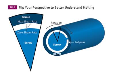
You can better visualize the melting process by “flipping” the observation point so that the barrel appears to be turning clockwise around a stationary screw.
Read MoreHow Polymer Melts in Single-Screw Extruders
Understanding how polymer melts in a single-screw extruder could help you optimize your screw design to eliminate defect-causing solid polymer fragments.
Read More














.png;maxWidth=970;quality=90)